
How the Soldano Super Lead Overdrive SLO-100 & 50 Watt Amplifiers Work
By Rob Robinette
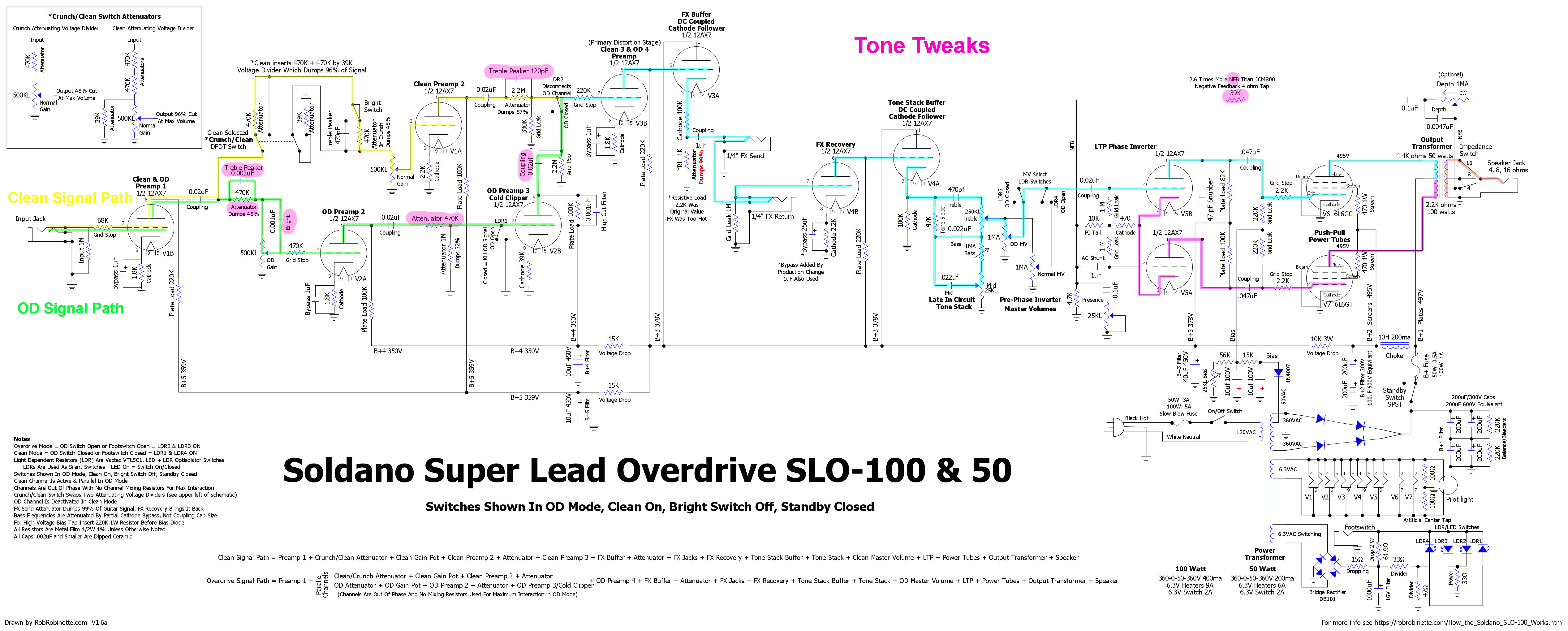
The Soldano Super Lead Overdrive SLO-100 was a breakthrough ultra-high gain guitar amplifier design. Mike Soldano was the first amp designer to discover that great overdrive tone can be coaxed from a cascading chain of relatively low gain preamp stages. The trick is to dump excess signal to prevent harsh sounding square wave over-overdrive and to moderate very low and very high guitar frequencies. Soldano controlled inter-stage gain with attenuating voltage dividers that dump up to 96% of the guitar signal to ground! Dumping large portions of the guitar audio to ground sounds counterintuitive for a high gain amp but it allowed Mike to add an additional gain stage beyond the Marshall JCM800 preamp without generating harsh square wave distortion. The use of a plate load bypass cap on the cold clipper stage and large preamp grid stop resistors keeps high frequencies in check and prevents ice pick and oscillation.
The main reasons the SLO-100 was a true breakthrough amp is it generates almost all distortion in the preamp then keeps things clean for the FX loop, tone stack and power amp.
The FX loop is placed after the primary preamp distortion triodes--the Clean & OD Preamp 4 and the FX Buffer--so effects are not distorted by preamp overdrive.
Like the JCM800, the SLO amps place the tone stack late in the preamp after the primary distortion triodes to prevent overdrive harmonics generated by harmonic and intermodulation distortion from getting through unfiltered by the tone controls.
The power amp was designed to stay clean to keep from distorting the signals from the preamp and FX Loop.
The SLO-100 is the 4x6L6GC 100 watt version. The SLO-50 is the 2x6L6GC 50 watt version. The SLO-30 is the 2x6L6GC 30 watt version.
If after looking at this page you feel you need some background information on how tube amps work see my How Tube Guitar Amps Work and How Vacuum Tubes Work pages.
Table of Contents
The Long Tail Pair Phase Inverter
Tweaking the Overdrive and Tone
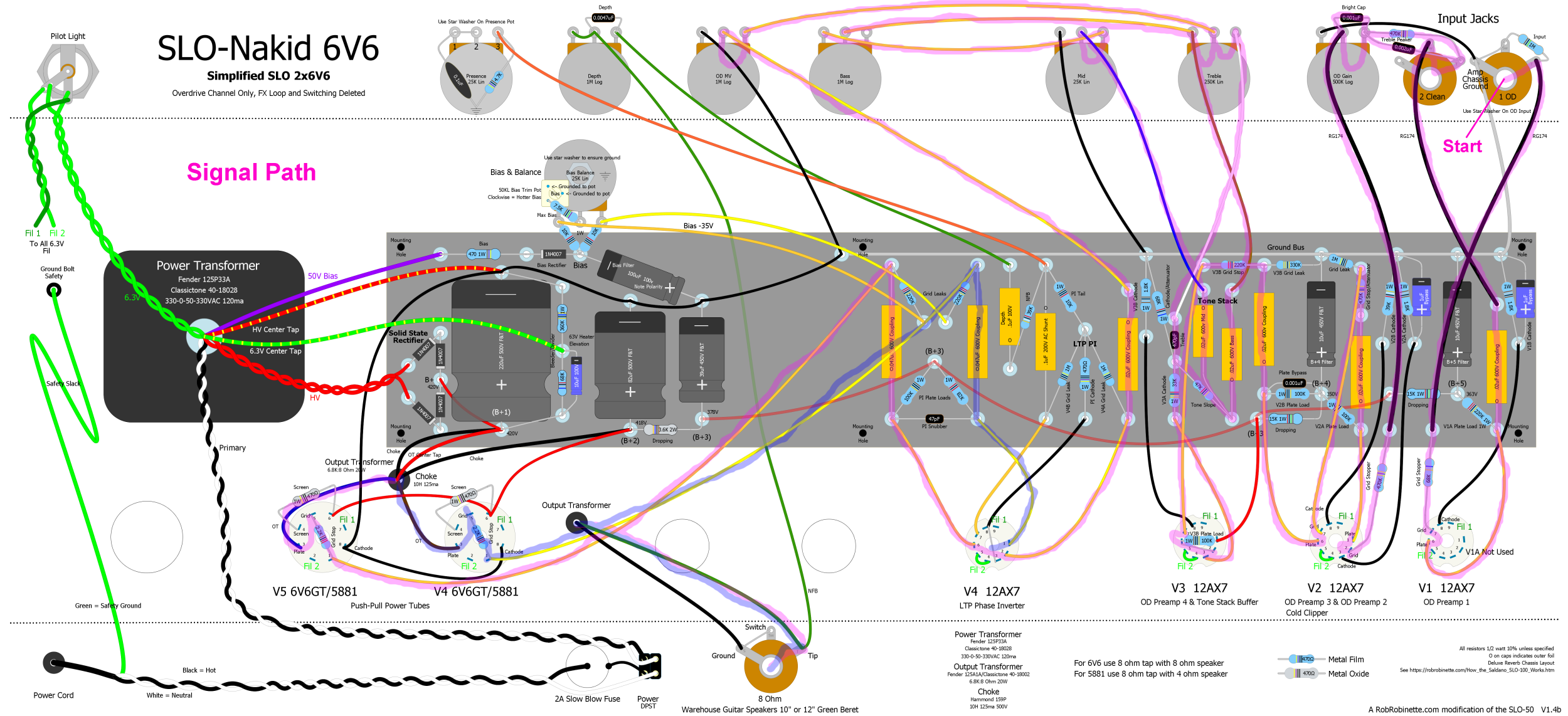
Simplified SLO-100 & 50 Schematic with OD Channel only and FX loop and switching deleted
SLO-Nakid 6V6 20 watt Simplified SLO 6V6 with OD Channel only and FX loop and switching deleted
SLO-Nakid 6L6 40 watt version of the SLO-Nakid
SLO-Nakid Micro EF80 Pentode 2 watt version of the SLO-Nakid with true push-pull small pentode power tubes
SLO-Nakid Micro 1 watt version of the SLO-Nakid with true push-pull 12AU7 power tube
Power Amp Boost Mod Hit the SLO-Nakid and Simplified SLO-100 power amp with a hotter signal for more power tube distortion
Channel Switching Soldano used Light Dependant Resistors (LDR) for silent switching.
Annotated Schematic
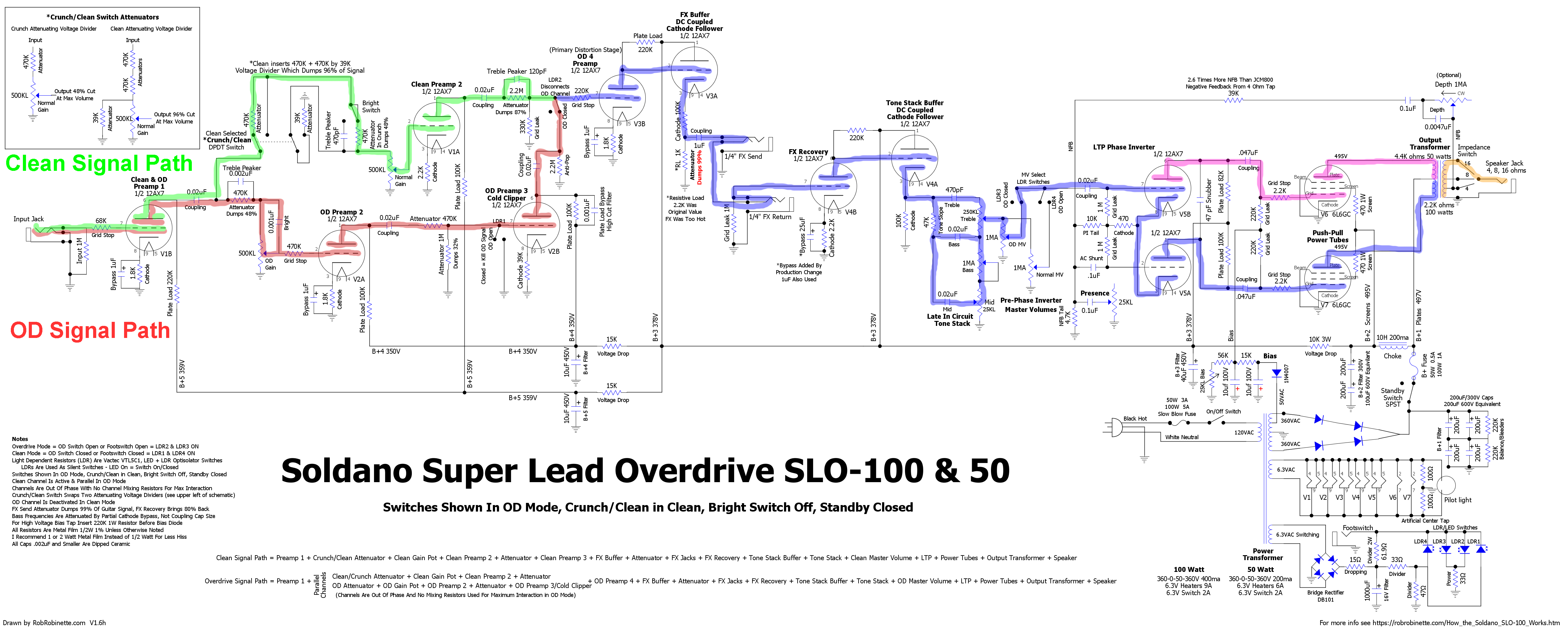
Every components' function is listed. Switches are shown in Overdrive Mode, Crunch/Clean switch in Clean, Bright switch off, Standby switch closed. When using the Clean Channel the Overdrive (OD) Channel is disconnected from the signal chain. When using the OD Channel both the Clean and OD Channel signal paths are active. The Clean Channel is out of phase with the OD Channel and when in Overdrive Mode the two channels are joined without mixing resistors for maximum interaction. The Clean Channel Crunch/Clean switch simply modifies an attenuating voltage divider (detailed at upper left box). Click the schematic to see the high resolution version, download the pdf file, download the DIYLC file.
SLO Circuit Board
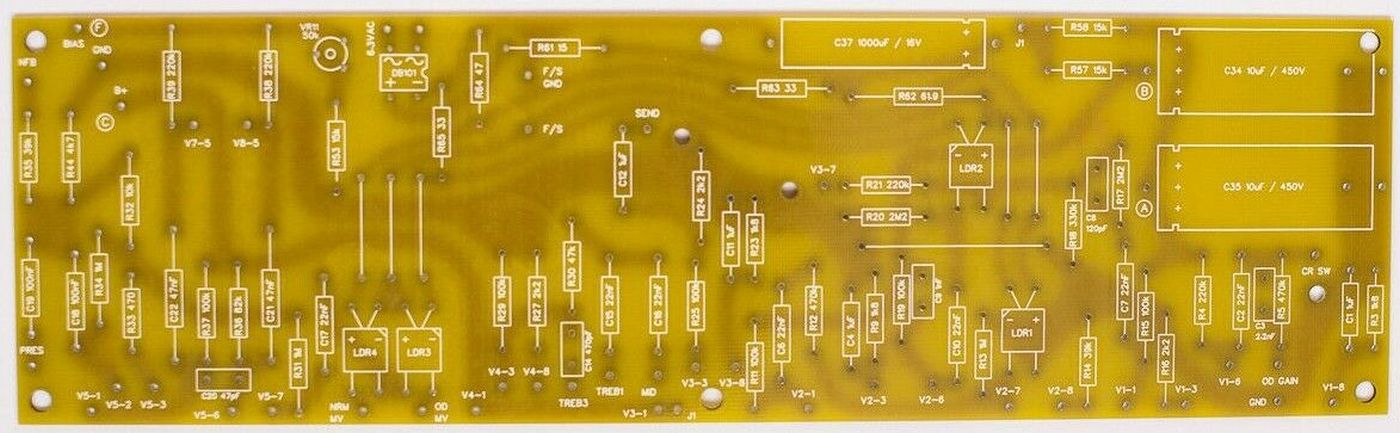
Tube socket connections are along the bottom of the board. DB101 (upper left) is the switching circuit bridge rectifier. C37 (top center) is the switching circuit filter cap. C34 and C35 (upper right) are the B+4 and B+5 filter caps. The LDR switches are the TV looking boxes labeled LDR1 through 4. The LDR + and - terminals are for (LED) switching power: power on = LED on and switch closed.
Signal Paths
Overdrive Channel signal path shown in red, Clean Channel shown in green. Click the image to see the high resolution version.
Overdrive Channel
Please refer to the red "OD Signal Path" in the schematic above. Both the Clean and Overdrive Channels use the first preamp stage (OD Preamp 1 at far left on schematic). It uses a 220k plate load resistor, 1.8k cathode resistor bypassed with a 1uF cathode bypass cap. The 220k plate load offers up more gain than the typical 100k plate load. The guitar audio signal leaves Preamp 1 and goes through a Soldano standard .02uF (22nF) coupling cap. As you can see in the frequency response graph below the cap passes the full spectrum of guitar frequencies. The lows are not trimmed by the cap. Compare the .02uF cap response to the .002uF coupling cap found in most high gain amps in the following chart.
SLO-100 Coupling Cap Frequency Response
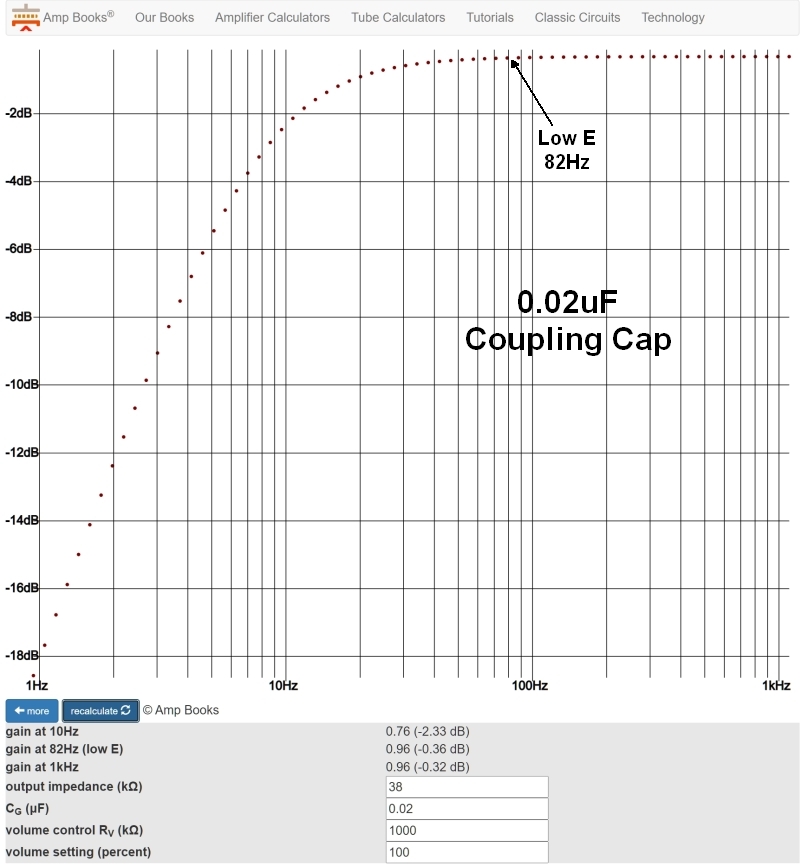
0.02uF coupling caps are used throughout the SLO-50 and 100. You can see that all guitar frequencies are passed unmolested through the coupling caps so they are not used for reducing low frequencies. Instead, Soldano used partially bypassed cathode resistors using 1uF bypass caps to trim excess lows (see below).
Smaller 0.002uF Coupling Cap Frequency Response
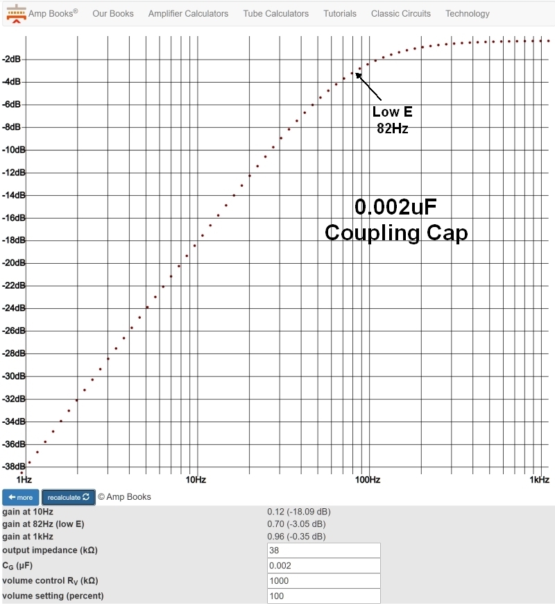
Most very high gain amps use a few 0.002uF coupling caps to trim & suppress low frequencies. The SLO amps do not use any 0.002uF caps.
Soldano made a conscious decision to trim low end frequencies with cathode bypass cap size (partial bypass), not coupling cap size. Soldano uses 1uF bypass caps throughout the SLO amps and as you can see in the graph below, low guitar frequencies are severely cut to keep the overdrive tone tight, prevent boomy lows and prevent blocking distortion.
SLO-100 1uF Cathode Bypass Cap Frequency Response
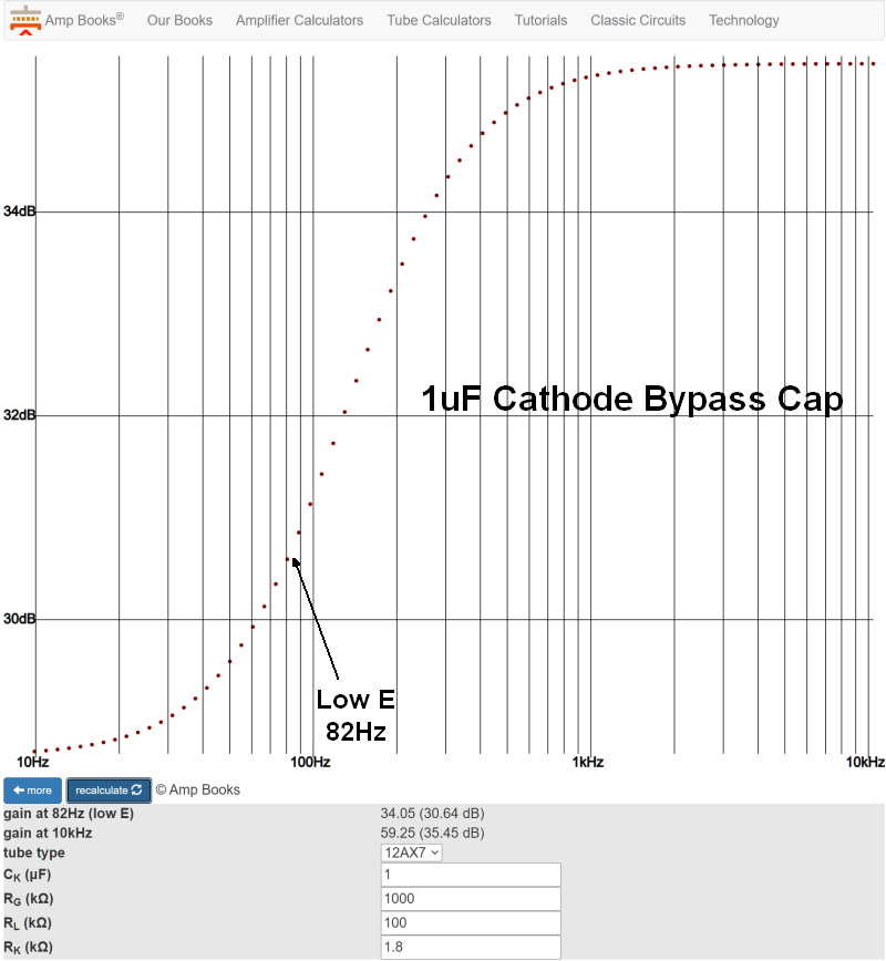
The SLO-50 and 100 preamp use several 1uF cathode bypass caps which give a partial cathode bypass. The lack of bypass for low frequencies subjects them to local NFB which not only attenuates low frequencies but helps keep them clean which limits low frequency intermodulation and harmonic distortion which can generate excessive and muddy lows. You can see that low guitar frequencies are trimmed and suppressed to keep the overdrive tone tight. Low frequencies will also push a gain stage into blocking distortion much earlier than mid and high frequencies. Soldano broke tradition and used cathode bypass cap size instead of coupling cap size to shape and control the low end.
The Attenuator Circuits
After the first stage coupling cap the OD guitar audio goes through the first attenuating voltage divider. The SLO-100 uses five attenuating voltage dividers to limit its cascading overdrive tone. Signal attenuating voltage dividers are present in all high gain tube amps to control the level of overdrive. Each SLO channel has one attenuator bypassed with a Bright cap (also called a treble peaker) to allow high frequencies to go around the divider to add high gain sizzle.
The first OD Channel divider is made up of a 470k Attenuator resistor + the 500k OD Gain pot. At maximum OD Gain volume this divider dumps 48% of the guitar signal to ground to keep from over overdriving the following gain stages. The Attenuator resistor is bypassed with a .002uF Treble Peaker to allow high frequencies to go around the voltage divider to boost high frequencies. Low and mid frequencies are cut by 48% by the attenuating voltage divider while high frequencies are not cut. If you remove or bypass the upper resistor in a voltage divider then there is no voltage divider. Removing this Treble Peaker cap is a common mod for overly bright amps to cut ice pick highs and reduce shrillness. There are four other attenuating voltage dividers in the OD and Clean Channels that moderate gain to keep things under control at high gain settings. The Crunch/Clean switch simply alters a voltage divider which dumps 48% of guitar audio in Crunch and 96% in Clean--yes, 96% of the guitar signal is dumped to ground by the Clean voltage divider.
After the first attenuating voltage divider the OD signal flows through a large 470k grid stop resistor which is paired with the following triode's Miller capacitance to form a low pass filter to trim some high frequencies. The large grid stop resistor also does a great job of preventing blocking distortion.
OD Preamp 2 is just like OD Preamp 1 except for the use of a more common 100k plate load resistor. Another .02uF coupling cap feeds another attenuating voltage divider. A 470k + 1M attenuator dumps 32% of the guitar signal, again to control gain to keep from over-overdriving the following gain stages. The 470k attenuator also functions as a large grid stop resistor to trim high frequencies and prevent blocking distortion. The signal then flows into the Cold Clipper stage.
The Cold Clipper
The cold clipper is very important to Marshall and Soldano high gain amps' smooth overdrive tone. For minimum distortion a tube should be biased halfway between cutoff (when all electron flow is stopped) and saturation (when electron flow is maxed out). A 1.5k cathode resistor for a typical 12AX7 gain stage is very close to center bias. The cold clipper's very large 39k cathode resistor sets a very cold bias that leaves little room on the shutoff side so the input signal can be easily distorted and clipped when the input signal's negative lobe on the grid reduces electron flow through the tube and electron flow is shutdown completely. This clipping is asymmetric because there's plenty of room on the saturation side of the bias point. Asymmetric clipping generates mostly sweet sounding 2nd harmonic distortion. The positive, saturation side of the guitar signal lobe isn't distorted and carries the original musical content.
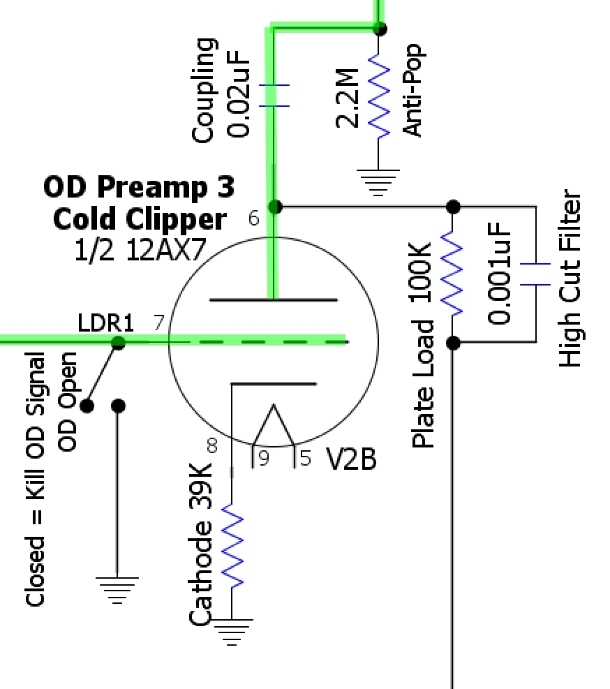
The SLO-100 uses a cold clipper stage with an unbypassed 39k cathode resistor. Marshall used a 10k cathode resistor for his cold clipper. The .001uF plate load bypass cap acts as a high cut filter to attenuate mid-highs and above to prevent downstream oscillation and ice pick highs.
Asymmetric clipping tends to sound smoother and creamier than symmetric clipping where both the + and - signal lobes are clipped equally. With asymmetric clipping one signal lobe carries the clean signal while the clipped lobe carries the distortion. The cold clipper generates early, relatively low volume, smooth, musical preamp distortion that can be controlled by the Master Volume for high gain tone at lower volume than earlier non-master volume amps. Without the cold clipper stage the preamp would stay too clean and the amp would have to rely on distortion from farther downstream. As the cold clipper distortion comes on it blends seamlessly into the downstream gain stages, cathode followers and power tube distortion into a cacophony of delicious high gain tone.
The cold clipper's asymmetric output signal can be clipped in later gain stages at high volume levels. The cold clipper is also a relatively low gain stage compared to one with a fully bypassed cathode. Soldano used the cold clipper cathode resistor value to trim gain to make his preamp work as desired. The higher the resistance value the lower the gain.
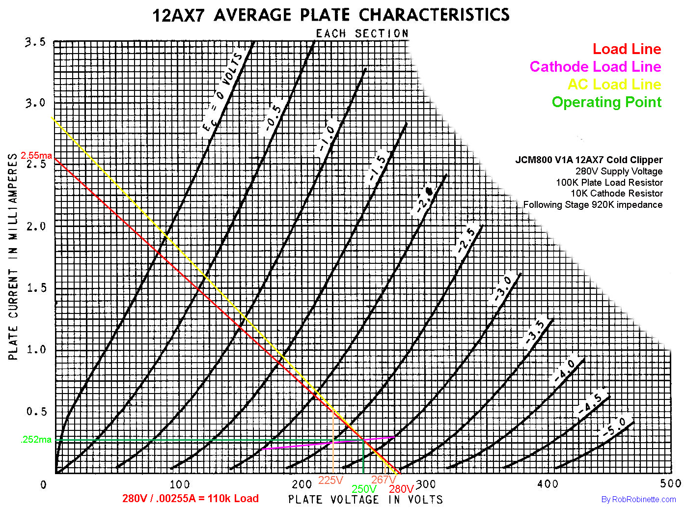
Soldano Cold Clipper Load Lines
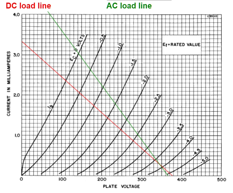
Low impedance (high load) downstream of 287k (2.2M || 330k) steepens the AC load line (in green above) for less gain compared to the Marshall below. The operating point (intersection of green and red lines) is very low in the curvy end of the grid voltage lines so the negative half of the guitar audio signal is distorted even before clipping occurs. Signal clipping will occur with the negative lobe of the signal voltage much earlier than the positive lobe which will lead to early sweet sounding asymmetric cutoff clipping. For information on how these lines were charted see How to Draw Load Lines.
Marshall Cold Clipper Load Lines
Cold Clipper Switch Mod
This is a cool little mod that allows you to select the 10k Marshall Cold Clipper, Soldano 39k Clipper or higher gain 4.4k cathode resistor.
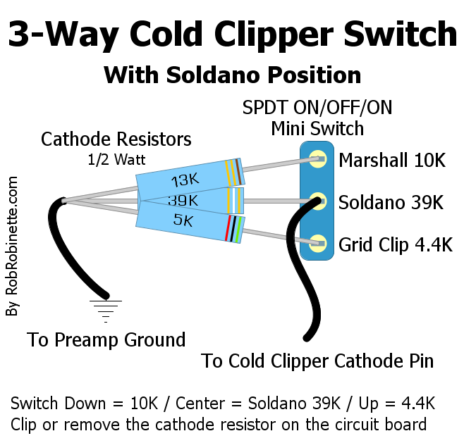
Down: 10k Marshall
Middle: 39k Soldano extra cold clipper
Up: 4.4k causes aggressive sounding grid clipping in the following stage (OD 4 Preamp).
The center 39k resistor is always active so when selected the 13k and 5k are in parallel with the 39k. 13k|39k = 10k and 5k|39k = 4.4k.
You can also put a cathode bypass cap across the 5k resistor for even earlier and more aggressive grid clipping in the following stage. The 3-Way Cold Clipper Switch lets you choose between two levels of cutoff clipping or more aggressive grid clipping. Most players do not like a bypass cap on a cold clipper because the extra signal swing generated by the bypass cap will distort too early and too severely and sound "fizzy".
The switch is a SPDT ON-OFF-ON switch. In the middle position only the middle resistor is connected. In the up and down position a resistor is in parallel with the center resistor so total resistance is their parallel resistance. You can also use the more common DPDT ON-OFF-ON switch and just use half the switch. The voltage across the switch is only 2 or 3 volts so its rating is unimportant. This switch will cause a pop which can be eliminated by turning the Master Volume full down before flipping the switch.

The Clean & OD Preamp 4 and its cathode follower are the first stages to go into overdrive so it is the primary distortion stage. It uses a 220k grid stopper to trim highs and prevent blocking distortion and a Soldano standard 1.8k cathode resistor with a 1uF bypass cap. The plate load is 220k to maximize gain.
The FX Buffer Cathode Follower is used to prevent FX pedals from loading down the high impedance guitar signal coming off the Clean 3/OD 4 preamp plate. A high impedance guitar signal is "thin" with little current to backup the voltage swing whereas a low impedance signal is "thick" with lots of current to backup the voltage. The Cathode Follower supplies a low impedance "thick" signal to the FX loop to keep FX pedals from loading down the audio signal and adversely affecting tone & volume.
But the FX Buffer Cathode Follower does much more than just feed the FX loop. It is the first triode to go into overdrive and its interaction with the upstream OD Preamp 4 gain stage adds a unique overdrive effect that limits clipping of both the positive and negative signal lobes. This is one of the "secret" reasons the Fender 5F6-A Bassman, Marshall JTM45, Plexi, Master Volume and Soldano amps sound so good when pushed hard. This interaction between a gain stage and cathode follower does not have a solid state equivalent.
Soldano placed the FX Loop after all the preamp distortion is generated to keep FX audio from being turned to mush by distortion. To get the guitar audio down to a suitable FX pedal level the FX Buffer output goes through an attenuating voltage divider that dumps an amazing 99% of the audio signal to ground. This voltage divider originally dumped 98% of the signal but the signal was still too hot for many FX pedals so a production change was implemented to cut the signal in half and dump 99% of the signal. This attenuator also delays power amp overdrive until very high gain and master volume settings.
The FX Recovery gain stage is used to recover about 80% of the gain lost to the FX loop attenuator but due to the 99% upstream signal dump this stage does not normally go into overdrive. Soldano did this so FX audio would not be distorted.
The Tone Stack Buffer Cathode Follower is used to prevent the tone stack from loading down the high impedance guitar signal (high voltage, low current) coming off the FX Recovery V4B plate. The Cathode Follower supplies a low impedance "thick" signal to the tone stack to keep the tone controls from affecting the amp's output volume too much. It has been said that the dual cathode follower design of the SLO amps is part of the wonderful overdrive formula but since the FX Recovery gain stage does not normally go into overdrive the Tone Stack Buffer Cathode Follower does not do any "magic" to the overdrive tone like the FX Buffer Cathode Follower does.
The Treble, Mid & Bass (TMB) Fender style tone stack uses variable RC filters to dump high, mid and low frequencies to ground. It's a passive tone control that cannot boost frequencies, only remove them from the guitar signal. It's a low impedance circuit that places a heavy load on the guitar signal so the Tone Stack Buffer Cathode Follower acts as a buffer between the low impedance tone stack and the high impedance signal from the preamp. Without the cathode follower the tone controls would raise and lower the overall signal volume even more than they already do. See How the TMB Tone Stack Works for more info. The Tone Stack is identical to the Marshall JCM800 stack except for the 47k Tone Slope resistor. The guitar signal leaves the tone stack through the treble pot's wiper and flows to the OD Master Volume pot. The position of the tone stack in the amp circuit is important. Soldano put it after the preamp and FX loop so the tone stack would work on everything--the original guitar signal, overdrive, harmonic and intermodulation distortion and FX pedals.
The Master Volume is a pre-phase inverter master volume versus the more common post phase inverter master volume (PPIMV). The pre-phase inverter master volume controls the signal level flowing into the phase inverter and controls the distortion level of both the phase inverter and the power tubes. The 12AX7 phase inverter gets hit with a hot signal from the preamp and being able to tame that signal before it hits the inverter's grid can help prevent unwanted blocking distortion at extreme volume levels. Again, Soldano chose this master volume to minimize power amp distortion to keep the audio signals from the FX loop clean. The down side of having the master volume on the input side of the phase inverter is you don't have the phase inverter's gain to create additional distortion before the master volume but this is not a problem for the very high gain SLO preamp.
The Clean Channel
Please refer to the green "Clean Signal Path" in the schematic above. The Clean Channel's guitar signal flows through Clean & OD Preamp 1 (same as the OD Channel) then splits away from the OD Channel. It flows to the Crunch/Clean Switch to select one of two attenuating voltage dividers (see box in upper left corner of the schematic). At max Clean Gain pot setting the Crunch attenuator dumps 48% of the guitar signal to ground to control gain while the Clean attenuator dumps an amazing 96% of the signal. After the attenuator and Clean Gain pot (with no bright cap) the signal flows into Clean Preamp 2 then another attenuating voltage divider that dumps 87% of the guitar signal. The 2.2M attenuating resistor is bypassed with a 120pF Treble Peaker to keep from losing too much high frequency and harmonics. The Clean signal then joins the Overdrive Channel at the Clean/OD Preamp 4 with no mixing resistors. With one less preamp gain stage than the Overdrive Channel the Clean Channel has more clean headroom and tends to be more pedal friendly than the Overdrive Channel.
In Clean Mode the OD Channel is disconnected and only Clean Channel audio flows through the amp but the Clean Channel is always on, even in Overdrive Mode. The Clean Channel is out of phase with the OD Channel due to their differing number of gain stages. The mixing of the Clean and OD channels in OD mode results in a slight attenuation of the OD audio signal.
How the Long Tail Pair Phase Inverter Works
The Long Tail Pair (LTP) Phase Inverter (also called the cathode-coupled phase inverter) is the most popular phase inverter in guitar amplifiers due to its large output voltage swing and sweet overdrive tone. Unlike the non-amplifying cathodyne phase inverter used in many guitar amps the LTP phase inverter not only creates a dual mirror image signal stream but it also acts as a gain stage boosting the signal by about 1/4 of what two normal triode gain stages would. This added gain gives its output more voltage swing to drive big bottle power tubes to a fully distorted state. The LTP is a true differential amplifier and uses both halves of a dual triode tube (usually a 12AX7or 12AT7).
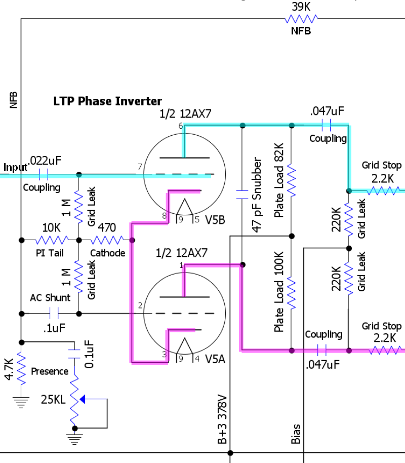
The LTP in the SLO-100 is identical to the Marshall Plexi, 2204, JCM800 and Fender 5F6-A Bassman amps. The signal enters the phase inverter at upper triode grid and flows out both its plate (inverted signal) and cathode (non-inverted signal). The guitar signal flows from the upper triode to the lower triode through their connected cathodes.
For simplicity I will refer to the LTP triodes as the "upper triode" and "lower triode".
The upper triode in the schematic above has a dual function. It acts as a normal gain stage by outputting an inverted signal at its plate but also acts like a cathode follower by outputting a non-inverted signal at its cathode.
In the schematic above the AC input signal flows through the .022uF coupling capacitor. The Coupling cap keeps the upper triode's 32.5v of DC grid voltage out of the master volumes and tone stack pots. This DC grid voltage is generated by the 10k PI Tail resistor. The signal then flows onto the upper grid while the lower grid is held at a constant DC voltage by the AC Shunt capacitor.
The upper and lower cathodes are tied together. All of the lower triode's input signal flows from the upper cathode. With the lower grid held constant by the AC Shunt cap, signal voltage fluctuations on the lower cathode alter the electron flow from the cathode to the plate which creates an amplified signal on the lower cathode's plate.
The tail resistor and presence circuit resistance creates the relatively high voltage (around 32.5v DC) needed for the cathode follower function of the upper cathode. It also supplies a near constant current flow shared between the two cathodes--as current increases through the upper cathode the current decreases through the lower and vice versa.
The 470 ohm cathode resistor creates a 1.5 volt difference between both tubes' grid and cathode. Its 470 ohm value shared between the two cathodes is the equivalent of each triode having a 940 ohm cathode resistor so the phase inverter is biased warm.
The grid leak resistors leak off DC grid current to maintain a steady DC bias voltage between the grid and cathode.
The plate load resistors are different values to balance the difference in gain between the upper and lower triodes.
The negative feedback signal from the output transformer 4 ohm speaker tap is injected into the LTP phase inverter in two places: the lower grid through the AC Shunt cap and the Tail resistor which leads to the cathode. The negative feedback signal on the lower grid counteracts the signal on the upper grid resulting in negative feedback attenuation. Injecting the NFB signal at the Tail resistor helps balance the feedback signal between the upper and lower triodes.
The Presence control removes a variable amount of high frequency from the negative feedback signal. Reducing negative feedback has the effect of boosting output so reducing the high frequencies in the negative feedback signal boosts high frequency output at the speaker. Not only are these high frequencies louder, they are "harrier" with added harmonics. Increasing the Presence cap value will lower the cutoff frequency and bypass a larger range of frequencies to ground therefore boosting a larger frequency range at the speaker output.
The 47pF Snubber cap between the LTP plates suppresses frequencies above human hearing to help stabilize the power amp circuit and prevent oscillation.
LTP and cathodyne phase inverters present a very high impedance to upstream circuits because their grid leak resistors are "bootstrapped" to the phase inverter tail resistor. The input signal on the grid is also present at the top of the tail resistor. This in-phase tail resistor signal reduces signal loss through the grid leak resistor which greatly reduces the load shown to the previous gain stage. Since impedance affects an audio filter's corner frequency we must use a much smaller coupling cap at the phase inverter grid to get the same low frequency roll off. This is why phase inverter input coupling caps can be so small. AB763 blackface head cab amps use a 500pF coupling cap. The .02uF cap used by Marshall and Soldano pass all bass guitar frequencies and could easily be reduced to .002uF with no effect on tone but decrease the likelihood of power tube blocking distortion.
Function Detail: When a positive voltage signal arrives at the upper grid the reduction of blocking electrons on the grid allows electrons to flow from its cathode, through the grid, to the plate. The electrons flowing onto the plate lowers the plate voltage--this is the inverted and amplified output signal. As electrons leave the upper cathode a positive voltage is created on the cathode (scarcity of electrons = positive voltage) caused by the voltage drop across the Cathode resistor. This positive signal voltage is also present in the lower cathode because the two cathodes are directly connected. Since the lower grid is held constant at 0 volts AC by the Shunt cap, any change in the cathode voltage will create a voltage difference between the grid and cathode. This voltage difference changes the flow of electrons from the cathode, through the grid to the plate. As the lower cathode goes positive (scarcity of electrons) fewer electrons will flow from it through the grid to the plate. The reduction of electrons flowing onto the plate raises the plate voltage--this is the non-inverted and amplified output signal.
SLO-100, JCM800 & 5F6-A Bassman LTP Phase Inverter Idle Voltage
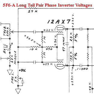
Note the voltage difference between the resistor junction of 32.5v and the cathodes at 34v equaling a normal bias for a 12AX7 of 1.5v. The voltage difference between the grids (22 and 23v) and the resistor intersection (32.5v) is measurement error caused by voltage probe circuit loading (if it were real the triodes would be in cutoff). Marshall's schematics show the same error with 24 and 25v shown on the phase inerter grids. Both grid voltages are actually the same as the resistor intersection at 32.5v for a bias voltage of 1.5v.
Here's an online calculator for determining the Balance of Output of the Long Tail Pair Phase Inverter.
Here's an online Long Tail Pair Negative Feedback Calculator .
The Power Amp
The simpler 50 watt power amp is shown below but the 100 watt power amp simply has two additional power tubes in parallel with the two shown below. The power and output transformers were also beefed up to handle the two extra tubes. The SLO-100 uses a 2.2k 100 watt output transformer while the SLO-50 gets a 4.4k 50 watt transformer.
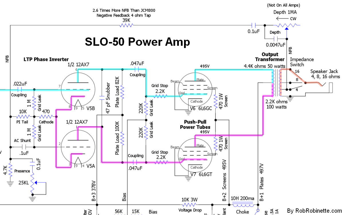
Guitar signal from the Phase Inverter enters the Power Tube Grids through the Grid Stop resistors. The signal is amplified and flows out the tube plates where one tube pushes the signal through the Output Transformer primary winding while the other power tube pulls. The high impedance signal (high voltage but low current) flowing through the Output Transformer primary winding induces a low impedance signal (low voltage but high current) in the secondary winding which is connected to the Speaker Jacks. The guitar signal then flows through the speaker's voice coil and generates a magnetic field. The magnetic field interacts with the speaker magnet and causes the voice coil and speaker cone to move in and out generating air pressure waves our ears perceive as the sweet sound of electric guitar.
Soldano wanted a relatively clean power amp so tightly controlled preamp distortion and FX audio would stay clean through the power amp. He used 6L6GC beam tetrode power tubes for their minimal screen sag compared to the high screen current and sag EL34 power tubes used in most Marshall amps. He also used a very high amount of negative feedback (2.6 times more NFB than the Marshall JCM800) to keep the poweramp clean.
The power supply's solid state rectifier and the use of a choke between the power tube plate and screen power nodes offers up minimal dynamic voltage sag to keep the overdrive tone tight and reduce the chance of power supply induced oscillation.
Soldano amps usually sound great with Marshall style green back speakers. I'm a fan of the Warehouse Speakers Green Beret.
Negative Feedback
The SLO-100 has 2.6 times more global negative feedback compared to the Marshall JCM800 and Master Volume amps with their 100k Negative Feedback (NFB) Resistor tapped from the 4 ohm speaker jack. Soldano used more NFB because he wanted a relatively clean power amp with most of the distortion created in the preamp.
The SLO-50 uses the same NFB circuit as the SLO-100 but the voltage at the SLO-50 4 ohm tap is 41% lower due to the reduced 50 watt output so the SLO-50 gets 41% less NFB which slightly loosens up the transition from clean to distortion and makes the overdrive tone a little less aggressive.
To drop a SLO-100's NFB to the SLO-50 level you can change the NFB resistor from 39k to 47k.
To increase a SLO-50's NFB to the SLO-100's level you can change the NFB resistor from 39k to 22k.
The Presence Control is a variable filter that removes high frequencies from the NFB loop. Cutting high freqs in the NFB loop will boost highs at the speaker. The highs will also be "harrier" with added harmonics.
The optional Depth Control is a variable filter that removes low frequencies from the NFB loop. This control is typically called a Resonance Control. Cutting low freqs in the NFB loop will boost lows at the speaker. The lows will also sound thicker with added harmonics. Speaker damping will also be reduced as low frequencies are removed from the NFB loop.
Channel Switching
Switching between the Overdrive and Clean Channels is done using 4 light dependant resistor switches (LDR) labeled LDR1 through 4 on the schematic. LDRs are used for soft switching with no clicks or pops. The Overdrive switch turns on LEDs that shine light on their paired light dependant resistor. No light shining on the LDR = high resistance/switch off/open. Light shining on the LDR = low resistance/switch on/closed. For Overdrive LDR 2 & 3 are lit/on/closed and 1 & 4 are off/open. For Clean LDR 1 & 4 are lit/on/closed and 2 & 3 are off/open. You should treat VTL5C1 LDRs as an LED and a switch. Add power to the LED to turn the switch on, remove power from the LED to turn the switch off. See the bottom right of the SLO schematic for the 6.3VAC switching power supply used by Soldano.
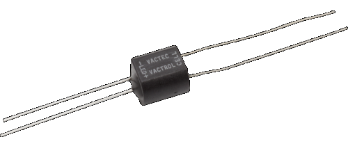
The VTL5C1 LDR will have LED polarity marked or have an angled corner that marks the LED negative terminal (LED cathode). The other end of the LDR will have the "cell" or switch leads which the guitar signal flows through. The resistance between these two leads is either 50M ohms (off) or very low (on).
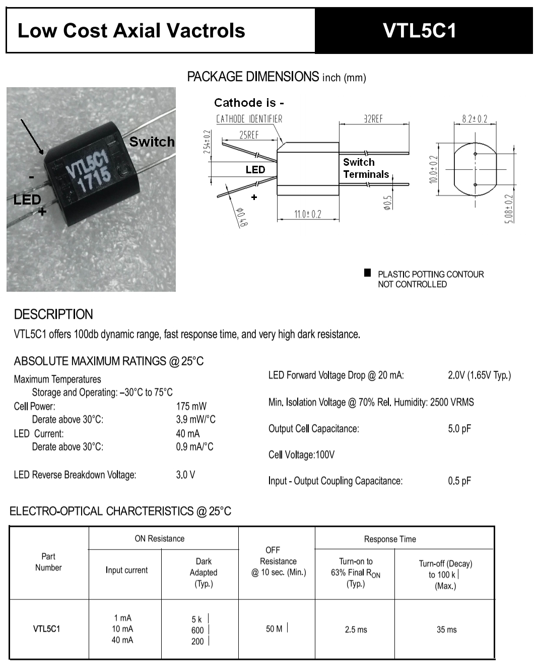
Note the angled corner which marks the LED end of the LDR and marks the negative terminal of the LED. The guitar signal flows through the other two terminals.
Tweaking the SLO-100 Overdrive Intensity and Tone
It's easy to adjust the SLO-100 preamp overdrive and tone by changing the value of a few components. These tweaks apply to both the SLO-100 and SLO-50.
The first Attenuator resistor located between Preamp 1 and the OD Gain pot can be increased to reduce preamp gain. The 470k Attenuator resistor and 1M volume pot form a voltage divider so increasing the Attenuator resistor will cut gain. Try a 560k or 680k there for less gain. If a 680k doesn't do enough then I recommend also adjusting the second Attenuator resistor located just before the 3rd preamp stage at the top of the circuit board. Try a 560k, 680k or even up to 1M to reduce preamp gain.
Increasing gain is more difficult in the SLO-100 because the preamp is already pushed near the limit of stability. Reducing the second Attenuator resistor located between Preamp 2 and Preamp 3 from 470k to 330k will add gain. If you alligator clip a 1M resistor in parallel with the 470k you'll get 320k to see if you like the mod. 270k will probably be too much gain but you can give it a try by clipping in a 680k in parallel.
If you need to tame the SLO-100 OD Channel high end you can reduce the value of the first Treble Peaker capacitor (in parallel with the first Attenuator resistor) from .002uF to .001uF or 500pF. The Bright cap on the OD Gain pot can also be reduced but keep in mind that cap only comes into play at lower volumes. Soldano used a .001uF Bright cap so try a 470pF, 330pF or even a 270pF cap.
To reduce brightness of the Clean Channel you can reduce or eliminate the Treble Peaker located after the Clean Preamp 2. It is already a low value at 120pF so try a 47pF or even clip it out entirely.
If you just need to reduce a little ice pick then an Ice Pick cap around the NFB resistor can do that without too much side effect on the overdrive tone. Its value can range from 47pF to 470pF, a higher value will cut more highs. You can alligator clip the cap in temporarily to find what you like.
If you are a very high gain player you can cut some low end by reducing the Coupling cap after Preamp 2 from .02uF to .002uF. This lower value was used by Marshall in many factory Plexi, Master Volume and JCM800 preamps.
Tweaks in magenta. Download the pdf.
Simplified SLO-100 & 50
Deleting the Clean Channel, FX Loop (including FX Buffer and FX Recovery triodes) and channel switching makes for a much easier amp build.
Schematic
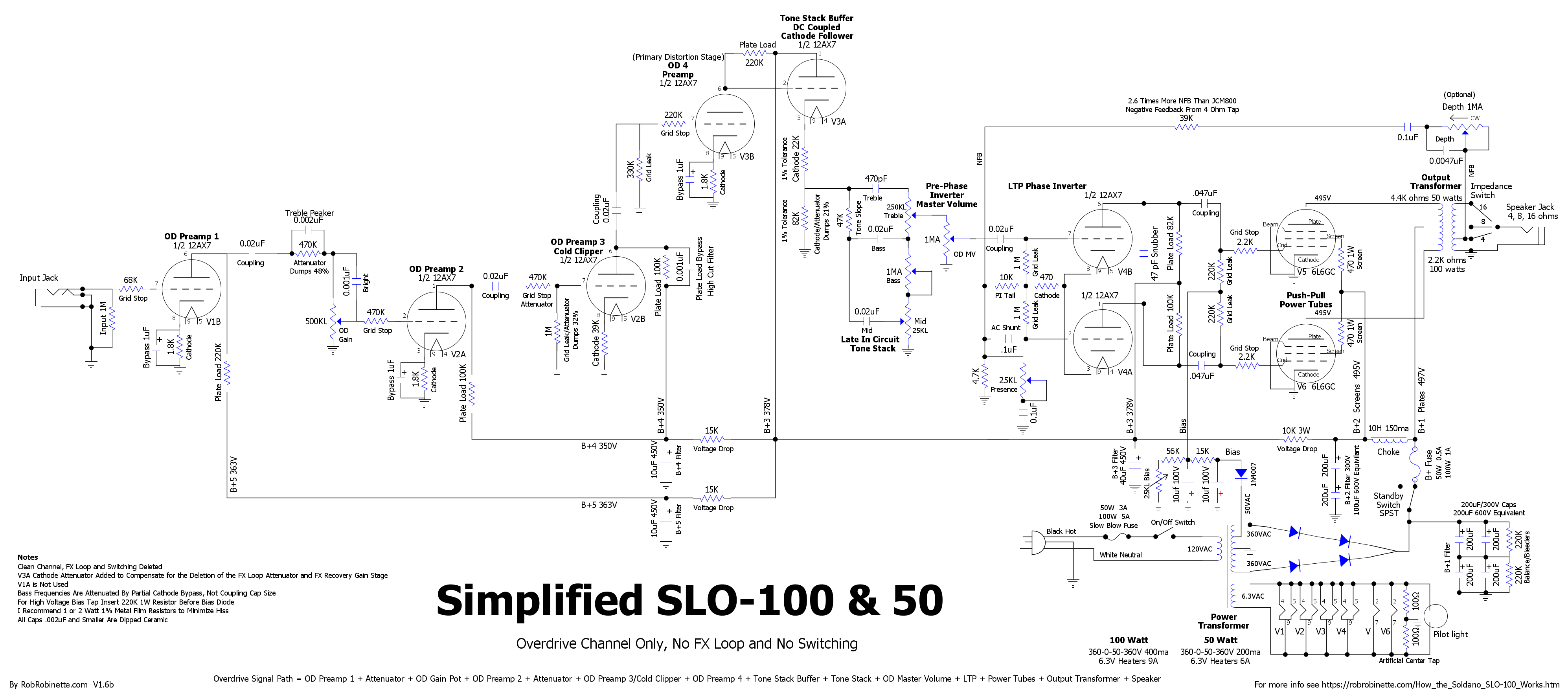
The V3A Tone Stack Buffer cathode resistor has been modified to form an attenuator to compensate for the deletion of the FX loop attenuator (99% signal cut) and FX Recovery gain stage (gain of 80). Note: If your power transformer does not have a 50v bias tap simply replace the bias circuit 470 ohm 1w resistor with a 220k 1w resistor and tap the high voltage for bias power. Click the image for the high resolution version. Download the pdf here and the DIYLC file here.
Signal Path
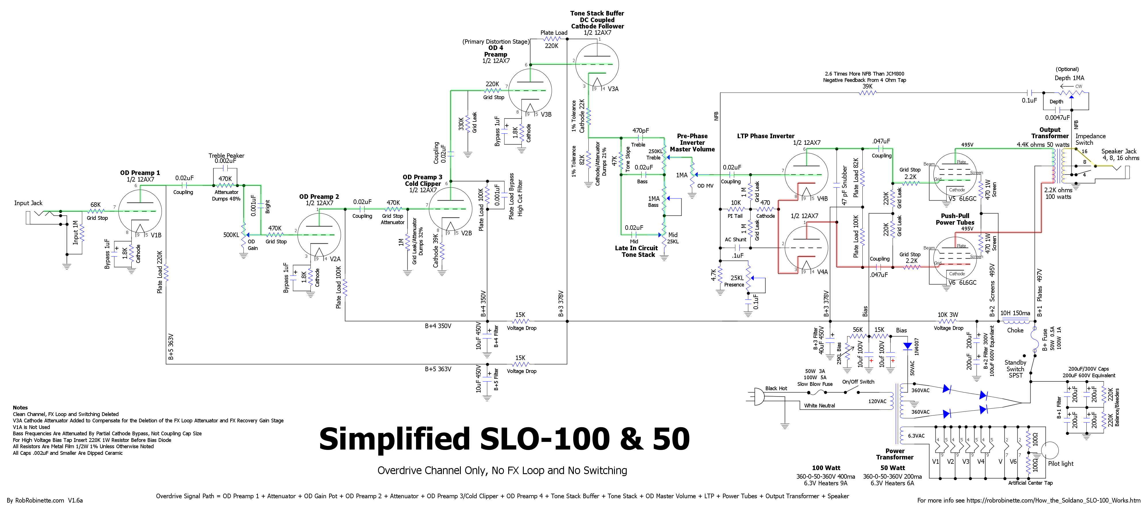
Signal path through the amp. Click the image to see the high resolution version. Download the pdf here.
SLO-Nakid 6V6 20 Watt
The SLO-Nakid 6V6 is a 2x6V6 20 watt amplifier based on the Simplified SLO-100 schematic above but laid out for a readily available Fender Deluxe Reverb chassis. It is a SLO amp with Overdrive Channel only with the FX loop and channel switching deleted. I added a JCM800 style "Clean" input jack that bypasses the first gain stage. I also added a heater elevation circuit to make life easier on the cathode follower and reduce hum. I also used my adjustable bias circuit with bias balance so you can balance unmatched power tubes or dial in some intentional mismatch to increase sweet sounding power tube second order harmonic distortion. If you don't want the power tube balance option feel free to use the original SLO-100 bias circuit shown in the schematic at the top of this webpage. The preamp is 100% SLO-100 Overdrive Channel.
The First SLO-Nakid Has Been Built
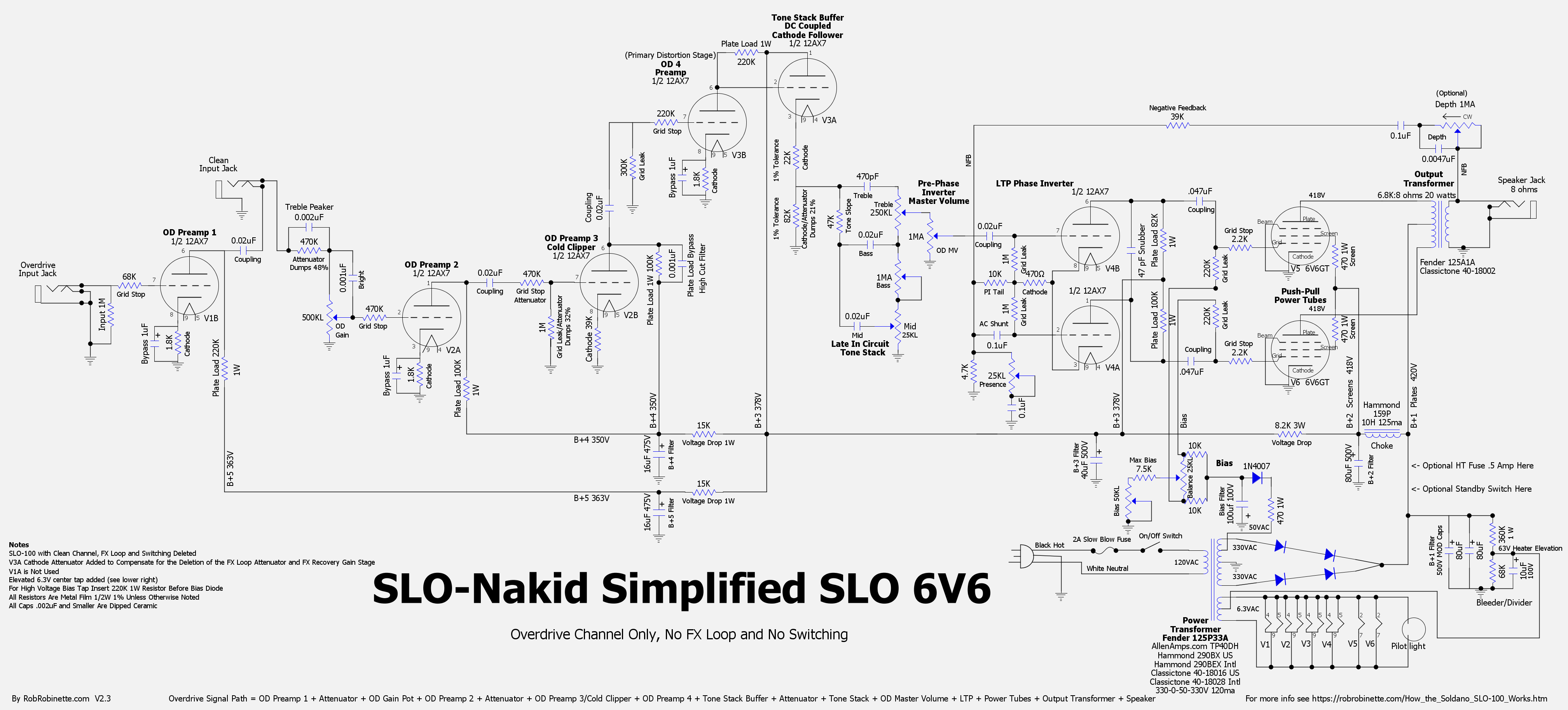
SLO-100 with 2x6V6 Power Tubes, Overdrive Channel only with FX Loop and Switching deleted. I added a "Clean" input that bypasses the OD Preamp 1 gain stage just like the JCM800 Low Input. I also added a heater elevation circuit at 63v. The V3A Tone Stack Buffer cathode resistor has been modified to form an attenuator to compensate for the deletion of the FX loop attenuator (99% signal cut) and FX Recovery gain stage (gain of 80). The first Voltage Drop resistor has been decreased from 10k to 8.2k to keep the preamp voltages at SLO-100 levels. Click the image for the high resolution version. Download the pdf file and DIYLC file.
SLO-Nakid Simplified SLO 6V6

Laid out for a Deluxe Reverb Chassis, power transformer and output transformer. The choke is a Hammond 159P 10H 125ma 500v. The first three filter caps are MOD 80uF 500v, the fourth is a MOD 40uF 500v but any 450v+ 40ish uF cap will work. Black lines on the caps indicate outer foil. Click the above layout for the high resolution version. Download the pdf file and DIYLC file. You can upload this HoffmanAmps.com SLO-Nakid circuit board file to the Doug Hoffman DIYLC file analyzer and Doug will make an eyelet or turret board for you for about $25. Revision 2.3 separated the preamp and poweramp ground busses to reduce noise.
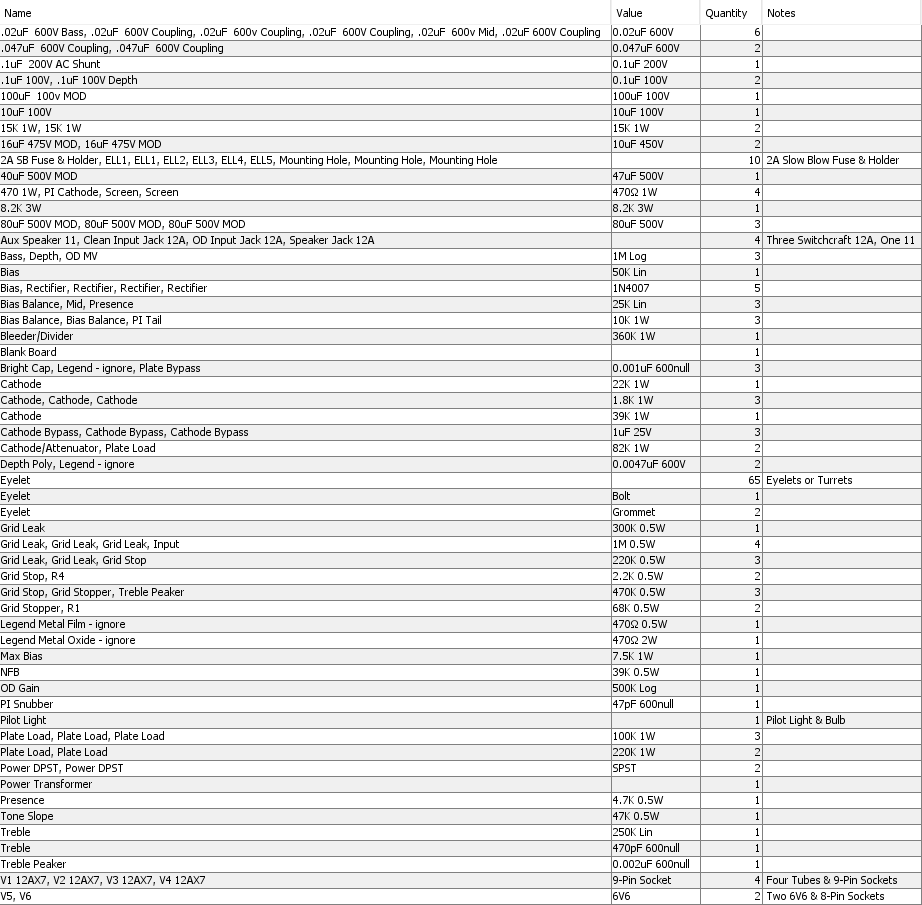
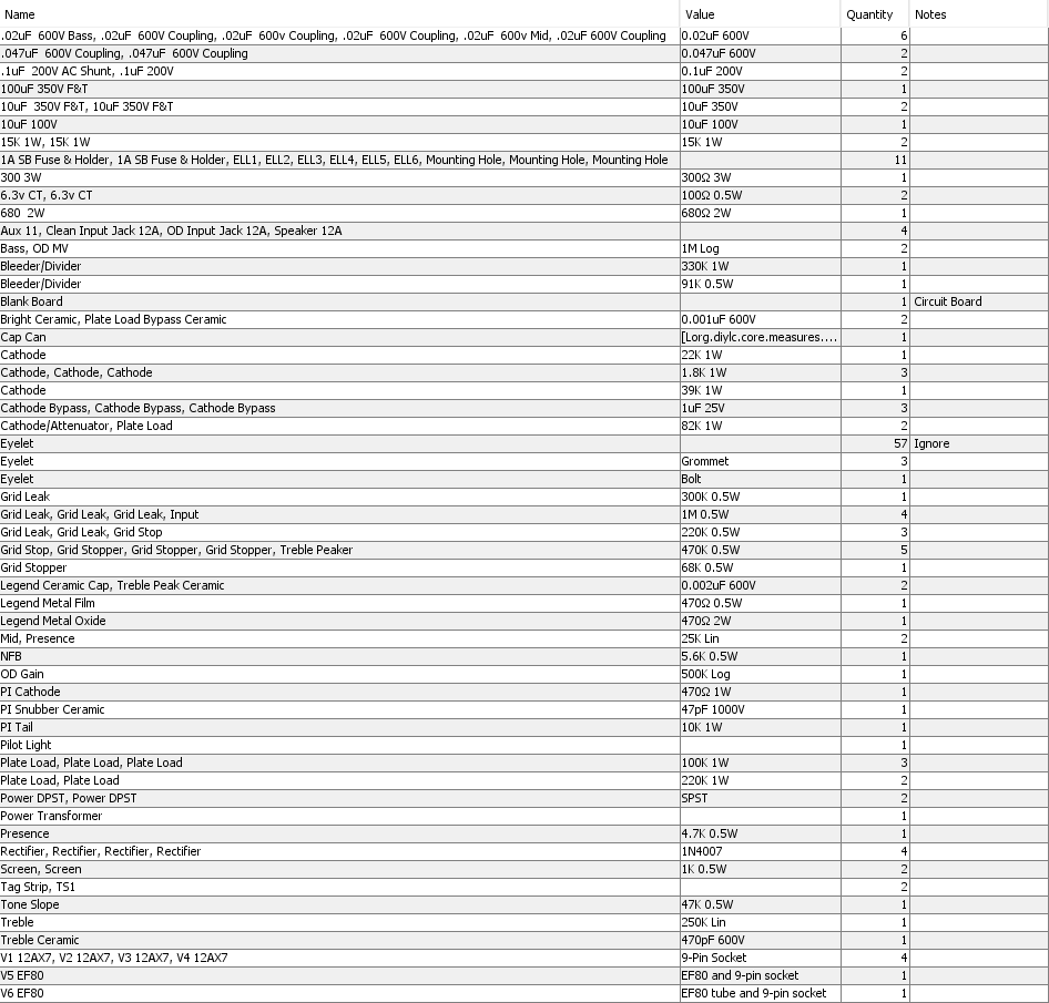
Bill Of Materials
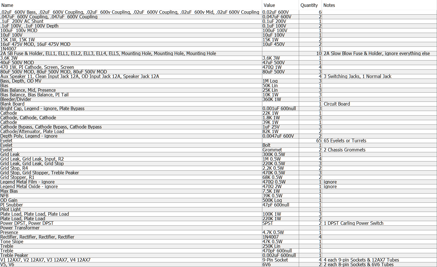
You'll also need an output transformer, cabinet, speaker and power cord.
Recommended Power Transformers
AllenAmps.com TP40DH Upgrade Deluxe Reverb power transformer supports 6V6 & 6L6GC. EL34 power tubes are supported by the transformer but the SLO-Nakid power tube sockets are not wired for EL34 tubes. NOTE: For EL34 compatibility tube socket pins 1 and 8 must be connected so the 2.2k grid stop resistor must be moved off pin 1. The 470 ohm screen resistor also needs to be upgraded to 1k 5 watt to handle the EL34's screen current during overdrive.
Fender 125P33A or equivalent
Classictone 40-18028 International
Hammond 290BX USA
Hammond 290BEX International
Any other Deluxe Reverb power transformer
Note: If your power transformer does not have a 50v bias tap simply replace the bias circuit 470 ohm 1w resistor with a 220k 1w resistor and tap the power transformer high voltage primary for bias power.
Recommended Output Transformers
AllenAmps.com TO26 Upgrade Deluxe Reverb output transformer supports 6V6 & 6L6GC
Fender 125A1A 6.8K:8 ohm 20 watt or equivalent
Any other 2x6V6 output transformer
Choke
Hammond 159P 10H 125ma 500v
Any other choke with 10H 75ma 450v minimum specification
Filter Caps
The MOD filter caps are available from Antique Electronic Supply (TubesAndMore.com).
Circuit Board
You can upload this HoffmanAmps.com SLO-Nakid circuit board file to the Doug Hoffman DIYLC file analyzer and Doug will make an eyelet or turret board for you for about $25.
Soldano amps usually sound great with Marshall style green back speakers. I'm a fan of the Warehouse Speakers Green Beret.
Elevated Heater Artificial Center Tap
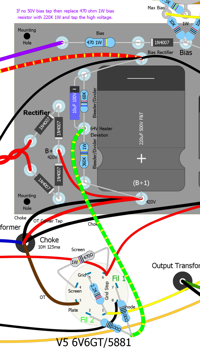
If your power transformer does not have a 6.3v heater center tap (typically a green/yellow wire) you can put an artificial center tap on the V5 power tube socket. Connect two 100 ohm 1/2 watt resistors from pins 2 and 7 (heater filament pins) to a point and connect the point to the 64v Heater Elevation eyelet/turret.
Signal Path
Signal path begins at upper right OD Input Jack and ends at speaker jack at lower center. It looks so much simpler on the schematic. Note: this is an old version of the layout.
Power Amp Boost Mod For SLO-Nakid & Simplified SLO-100
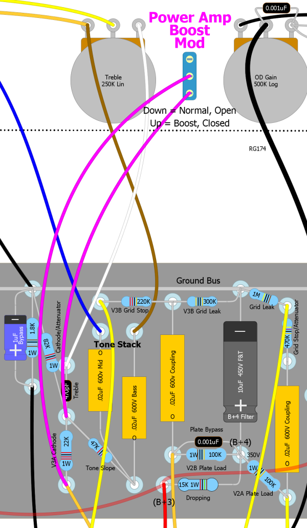
This switch allows you to bypass the Tone Stack Buffer 22k cathode/attenuator resistor which eliminates the attenuating voltage divider for a 21% boost in signal going into the phase inverter and power amp. This gives you more power tube distortion than the standard SLO-100. Keep this switch off when using FX pedals to prevent the power amp from distorting the FX signal. This mod works with the SLO-Nakid 6V6 and 6L6 but does not apply to the SLO-Nakid Micro (below) because the little power tube is already hit very hard with input signal.
SLO-Nakid 6L6 40 Watt
The SLO-Nakid 6L6 is a 2x6L6 40 watt amplifier based on the Simplified SLO-100 schematic above but laid out for a readily available Fender blackface 2x6L6 chassis such as the Bandmaster. It is a SLO amp with Overdrive Channel only with the FX loop and channel switching deleted. I added a JCM800 style "Clean" input jack that bypasses the first gain stage. I also added a heater elevation circuit to make life easier on the cathode follower and reduce hum. I also used my adjustable bias circuit with bias balance so you can balance unmatched power tubes or dial in some intentional mismatch to increase sweet sounding power tube second order harmonic distortion. If you don't want the power tube balance option feel free to use the original SLO-100 bias circuit shown in the schematic at the top of this webpage. The SLO-Nakid 6L6 uses the same circuit board as the SLO-Nakid 6V6 but with upgraded transformers and screen resistors. The preamp is 100% SLO-100 Overdrive Channel.
SLO-Nakid 6L6 Demo
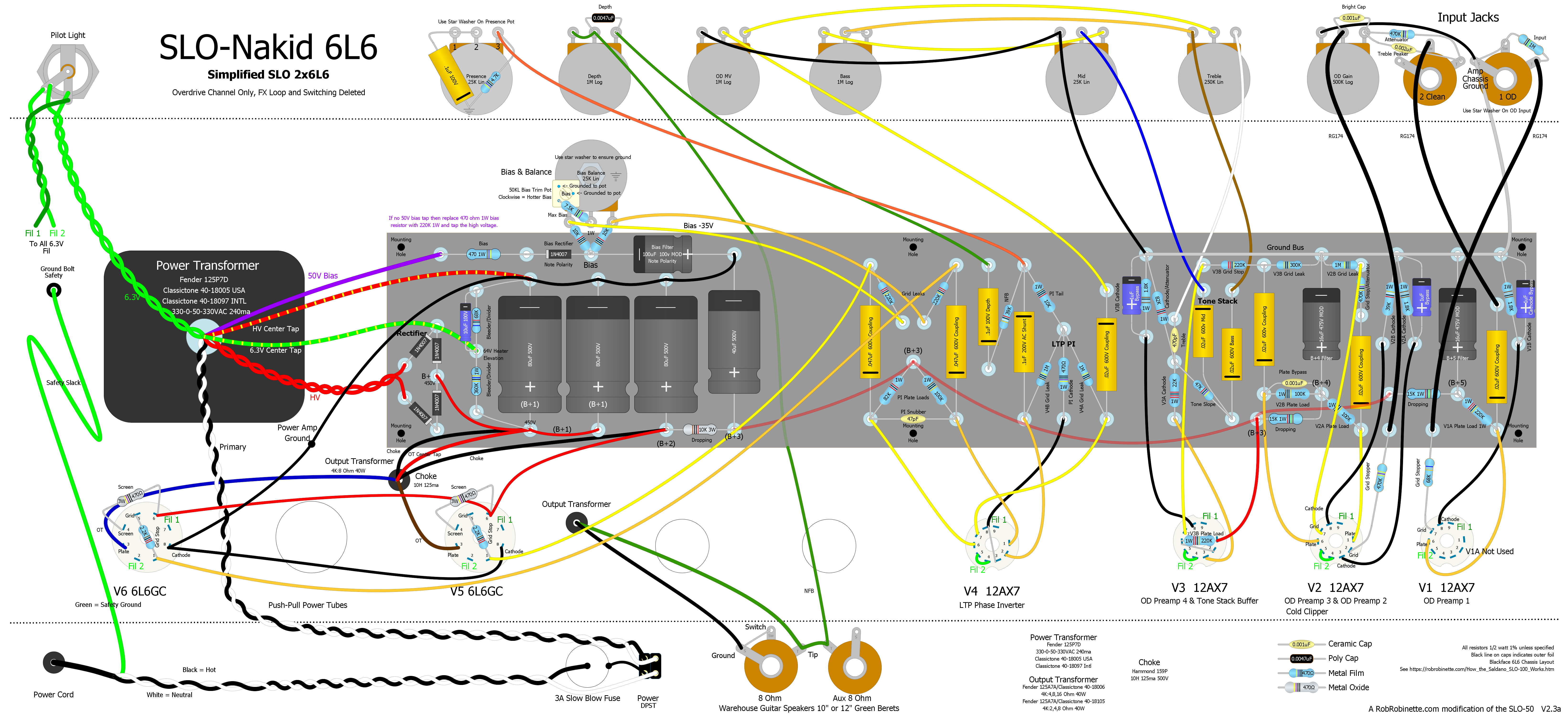
Laid out for a 2x6L6 blackface chassis and blackface power transformer and output transformer. The choke is a Hammond 159P 10H 125ma 500v. The first three filter caps are MOD 80uF 500v, the fourth is a MOD 40uF 500v but any 450v+ 40ish uF cap will work. Black lines on the caps indicate outer foil. Click the above layout for the high resolution version. Download the pdf file and DIYLC file. You can upload this HoffmanAmps.com SLO-Nakid circuit board file to the Doug Hoffman DIYLC file analyzer and Doug will make an eyelet or turret board for you for about $25. Revision 2.3 separated the preamp and poweramp ground busses to reduce noise.
Bill of Materials
You'll also need an output transformer, cabinet, speaker and power cord.
Recommended Power Transformers
The SLO-Nakid power tube sockets are not wired for EL34 tubes. For EL34 compatibility tube socket pins 1 and 8 must be connected so the 2.2k grid stop resistor must be moved off pin 1. The 470 ohm screen resistor also needs to be upgraded to 1k 5 watt to handle the EL34's screen current during overdrive.
Fender 125P7D 330-0-50-330VAC 240ma or equivalent
Classictone 40-18005 USA
Classictone 40-18097 International
Note: If your power transformer does not have a 50v bias tap simply replace the bias circuit 470 ohm 1w resistor with a 220k 1w resistor and tap the power transformer high voltage primary for bias power.
Recommended Output Transformers
Fender 125A7A 4K:8 ohm 40 watt or equivalent
Classictone 40-18006
Any other 2x6L6 output transformer
Choke
Hammond 159P 10H 125ma 500v
Any other choke with 10H 75ma 450v minimum specification
Filter Caps
The MOD filter caps are available from Antique Electronic Supply (TubesAndMore.com).
Circuit Board
You can upload this HoffmanAmps.com SLO-Nakid circuit board file to the Doug Hoffman DIYLC file analyzer and Doug will make an eyelet or turret board for you for about $25.
Soldano amps usually sound great with Marshall style green back speakers. I'm a fan of the Warehouse Speakers Green Beret.
Elevated Heater Artificial Center Tap
If your power transformer does not have a 6.3v heater center tap (typically a green/yellow wire) you can put an artificial center tap on the V5 power tube socket. Connect two 100 ohm 1/2 watt resistors from pins 2 and 7 (heater filament pins) to a point and connect the point to the 64v Heater Elevation eyelet/turret. You can place a terminal strip near the tube socket to anchor the resistor junction.
SLO-Nakid Micro EF80 Pentode 2 Watt
This is the 2 watt push-pull pentode power tube version of the SLO-Nakid with Overdrive Channel only and the FX Loop and Switching deleted. It is designed to use a Princeton Reverb chassis. The preamp is still 100% SLO-100 but the power amp was modified to run a pair of small 9-pin EF80 pentode power tubes in true push-pull. Builders have been asking for a micro power amp using a small pentode because pentode overdrive tone is different than triode overdrive tone. A pentode's screen grid generates a distinct power tube distortion so this power amp should sound more like a full size amp than one using triode power tubes such as the 12AU7.
The power transformer, power supply and output transformer were changed to suit the EF80 power tubes. The power tube grid stop and grid leak resistors were rearranged to form an attenuating voltage divider that dumps 32% of the signal to keep from overwhelming the little power tubes. The NFB resistor value was decreased to compensate for the lower output transformer secondary voltage.
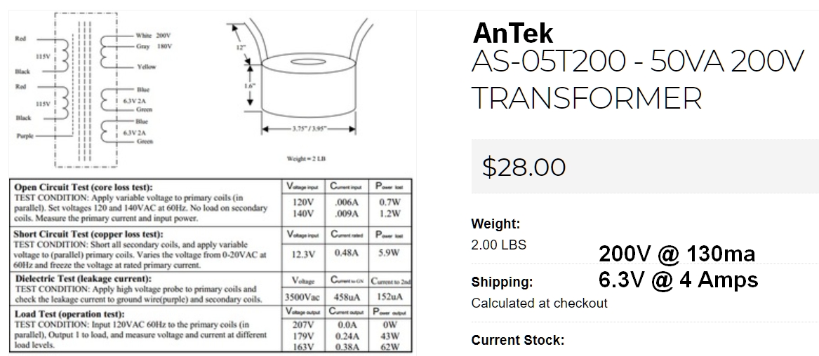
My recommended power transformer is this inexpensive $28 AnTek AS-05T200 toroidal power transformer 200v @ 130ma (50VA), 6.3v @ 4 amps. It must be used with a bridge rectifier. You can build the bridge rectifier with two tag strips and four 1N4007 diodes or get an inexpensive bridge rectifier like this $1 three amp 1000v bridge rectifier from Mouser. The AS-05T200 has a 120v and 240v primary (240 primary is good for 220 to 250v mains). It also has a 180v tap in case you want to lower the amp voltages (use gray and yellow wires for 180v of HT). Another bonus is it only weighs 2 lbs. Size is 3.75" in diameter and 1.6" tall. You can mount the transformer on the top of the chassis and purchase a 105x45mm round transformer cover, leave it exposed or mount it inside. Mounting consists of drilling a single hole for the transformer central bolt.
![]()
Detailed AnTek Wiring
![]()
If you would prefer to use a "normal" (non-toroid) power transformer then I suggest the $89 Hammond 269EX 190-0-190V power transformer with 190-0-190 high voltage at 75ma, 2.5 amps of 6.3v heater current. For international builders I recommend the Hammond 369EX which has 100, 110, 120, 200, 220,230, 240 VAC 50/60 Hz primaries. The 269EX/369EX is a good choice for any amp using an EF80 power amp but it does not include a 5v secondary so if you want to use a tube rectifier use an EZ81 (6.3v).
Hammond 269EX/369EX Power Transformer
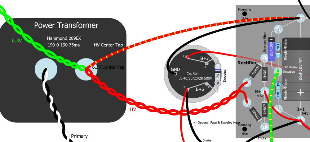
Note the position of the HV center tap and the full wave conventional rectifier wiring.
New Old Stock EF80s (also called 6BX6) are inexpensive ($6) and plentiful but tend to be microphonic so they are best used in head amps and not combo cabs. If you do use them in a combo cab expect to have to try several tubes to find a pair that are not microphonic. Using rubber insulated sockets and silicone damping rings on the tubes may help with microphonics. The EF80 uses standard 9-pin sockets and 6.3v heaters so they are easy to implement into a modern amp build.
At 270 to 300v on the plates and a 300 ohm cathode resistor (as in the layout below) you can expect about 5.2v across the cathode resistor with the EF80s running at 2.45 watts, 95% plate dissipation with 8.4 milliamps of plate current per tube. Adding a 1k 1/2 watt screen resistor will add some screen sag distortion and emphasize the difference between triode and pentode overdrive.
Doug Hoffman at HoffmanAmps.com can make you a SLO-Nakid Micro EF80 turret or eyelet board using this Hoffman Board File for about $20 + shipping. Just go to the HoffmanAmps DIYLC Analyzer page and upload the SLO-Nakid Micro Hoffman Board File.
If you like this amp but want a little less gain and more versatility check out the JCM800 Micro EF80.
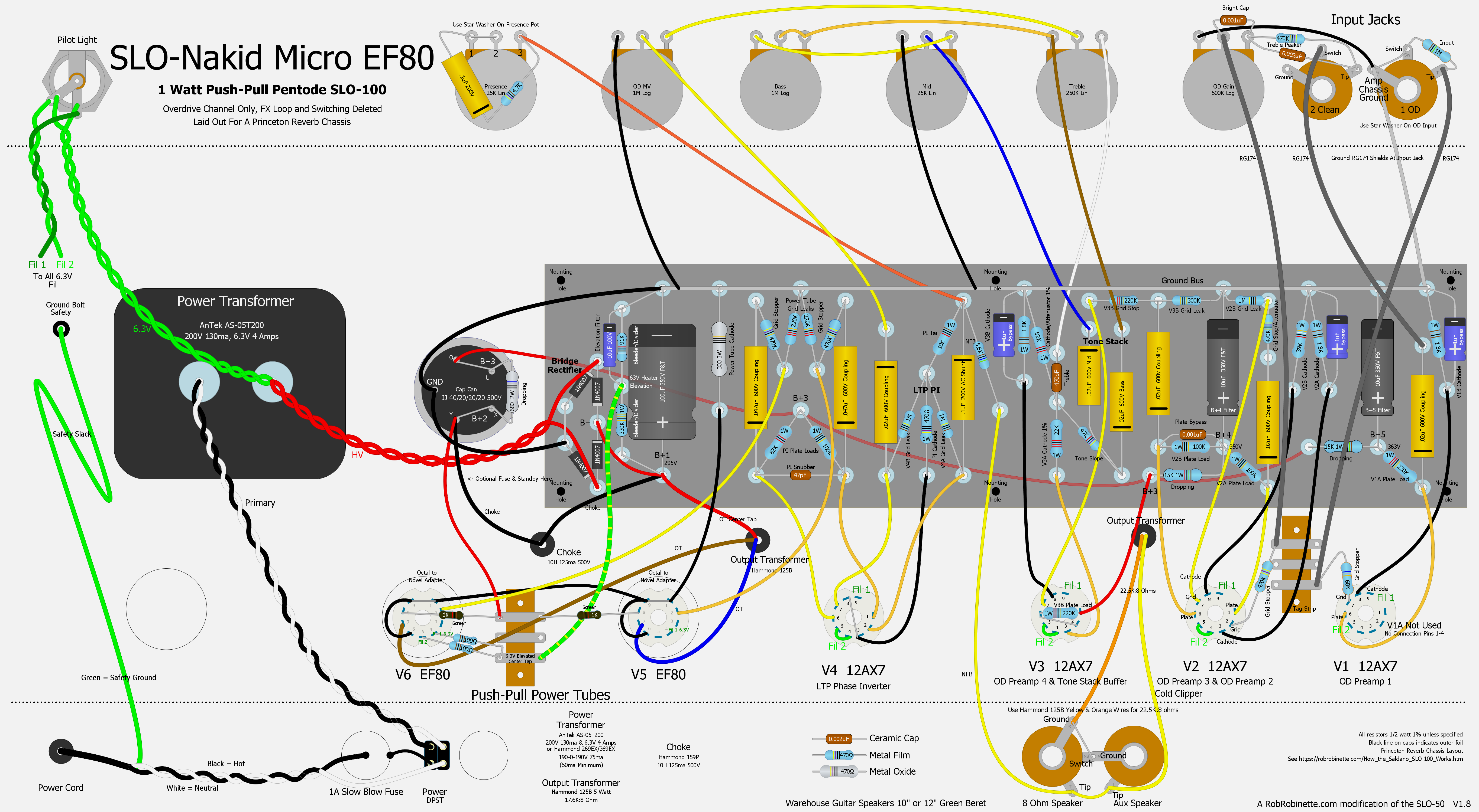
Click the layout above to see the high resolution version, download the layout pdf, DIYLC file and Hoffman board file.
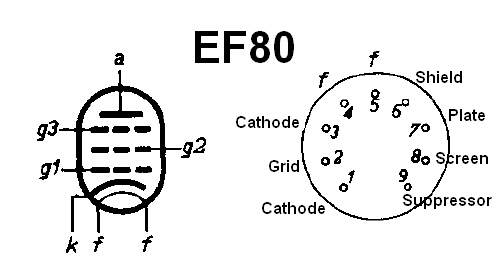
Pins 1 & 3 connect to a single cathode, pins 4 & 5 (f) are 6.3v heater filaments, pin 6 is an internal shield which is normally connected to the cathode or ground, pins 1 & 9 (cathode and suppressor grid) are normally tied together.
Hammond 125B Output Transformer Wiring & Specs
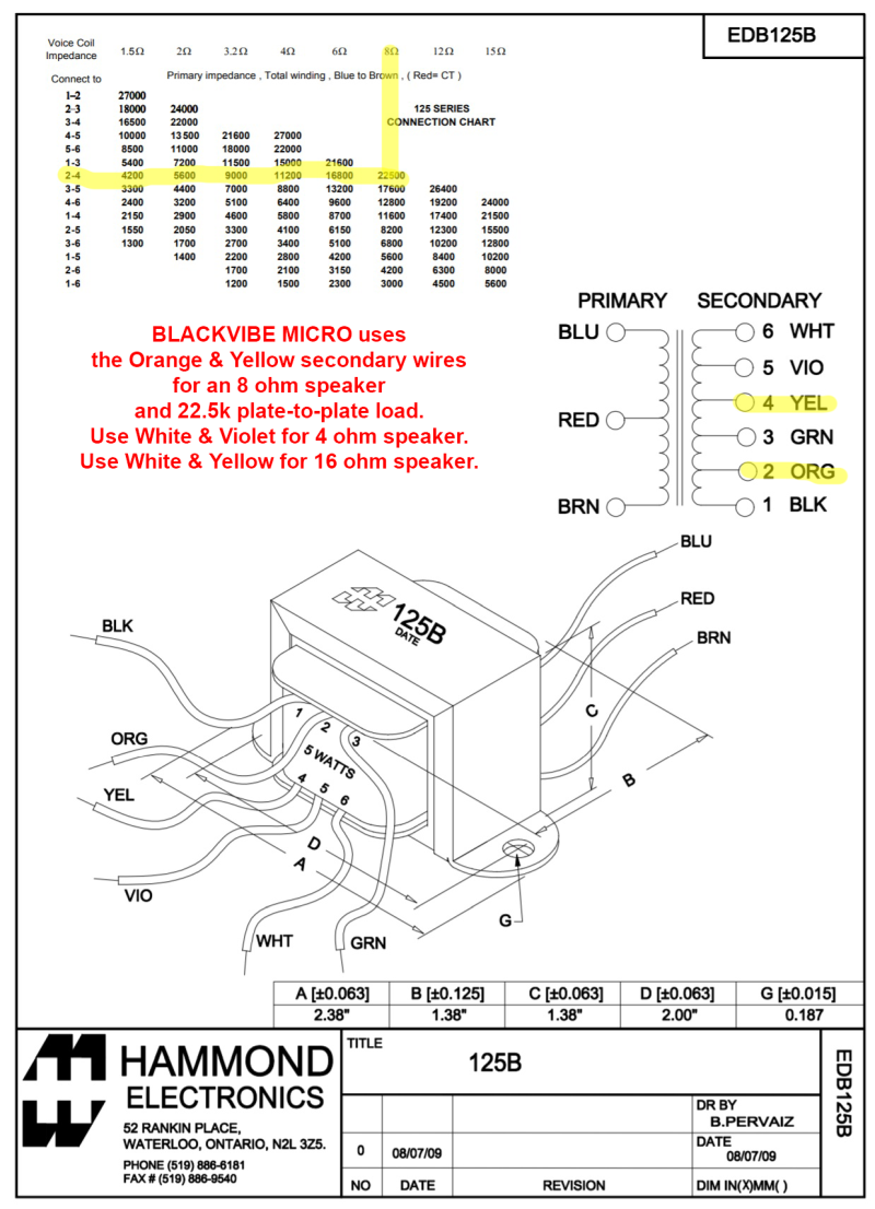
For the EF80 we want 22,500:8 ohms so we use the Yellow (4) & Orange (2) wires. We do not use the Black secondary wire.
![]()
Another (better looking) option for the output transformer is the $29 MusicalPowerSupplies.com OT5PP 22.5K:4-8-16 ohms.
Bill of Materials
You will also need a Hammond 125B output transformer, Hammond 155H 4H choke, chassis, cab, speaker and power cord.
EF80 Power Amp

This is the Blackvibe Micro EF80 but the power amp is identical to the SLO-Nakid EF80.
SLO-Nakid Micro 1 Watt
This is the 1 watt version of the SLO-Nakid above with Overdrive Channel only and the FX Loop and Switching deleted. It is designed to use a Princeton Reverb chassis. The preamp is still 100% SLO-100 but the power amp was modified to run a single 12AU7 power tube in true push-pull. The power transformer, power supply and output transformer were changed to suit the 12AU7 power tube. The power tube grid stop and grid leak resistors were rearranged to form an attenuating voltage divider that dumps 68% of the signal to keep from overwhelming the little power tube. The NFB resistor value was decreased to compensate for the lower output transformer secondary voltage. Since the 12AU7 is a triode with no screen I deleted the B+2 screen power node. The choke has been moved upstream and now filters the entire amp circuit.
SLO-Nakid Micro
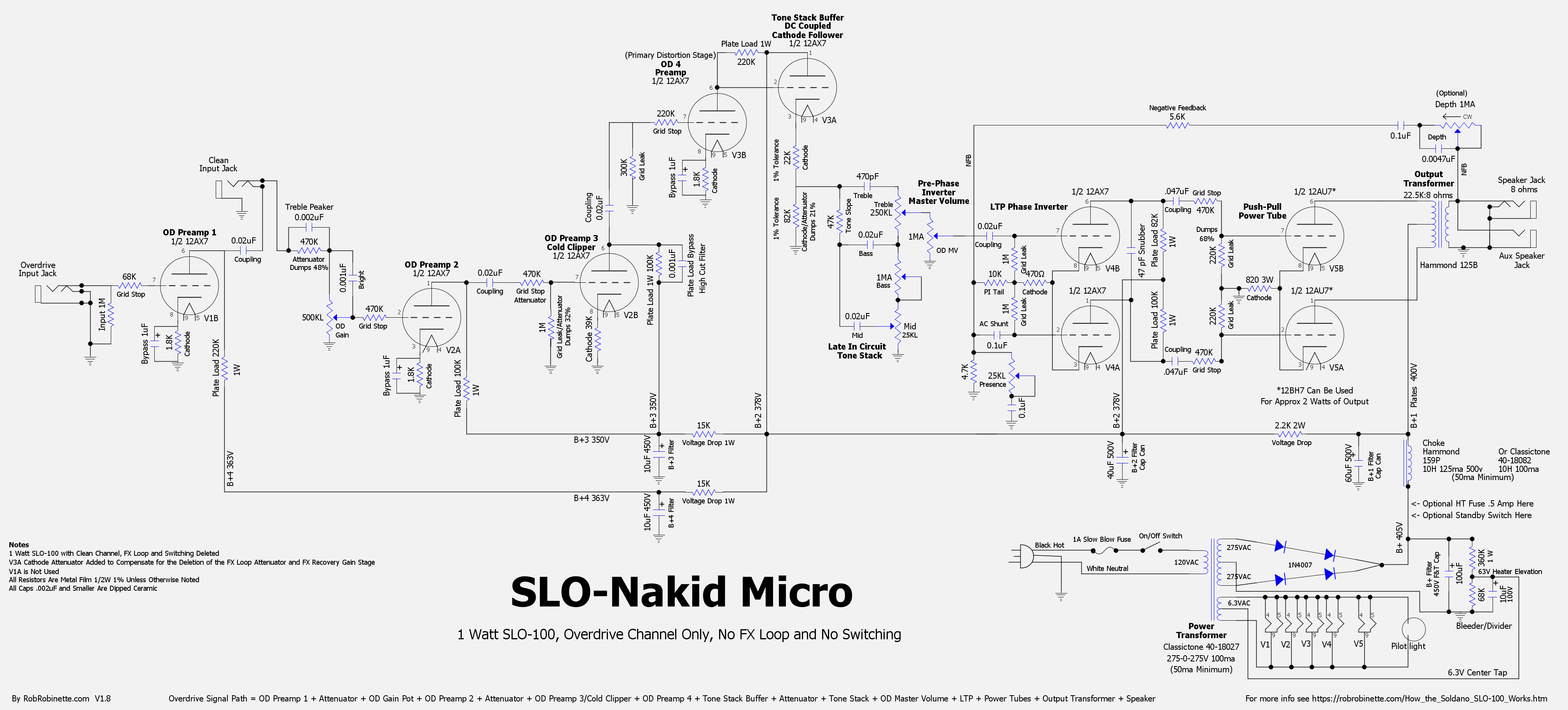
A JCM800 style "Clean" input jack has been added which bypasses the first gain stage. The two 12AU7 (or 12BH7) triodes are used in true push-pull. Click the image to see the high resolution schematic, download the pdf here and download the DIYLC file here.
SLO-Nakid Layout For Princeton Reverb Chassis
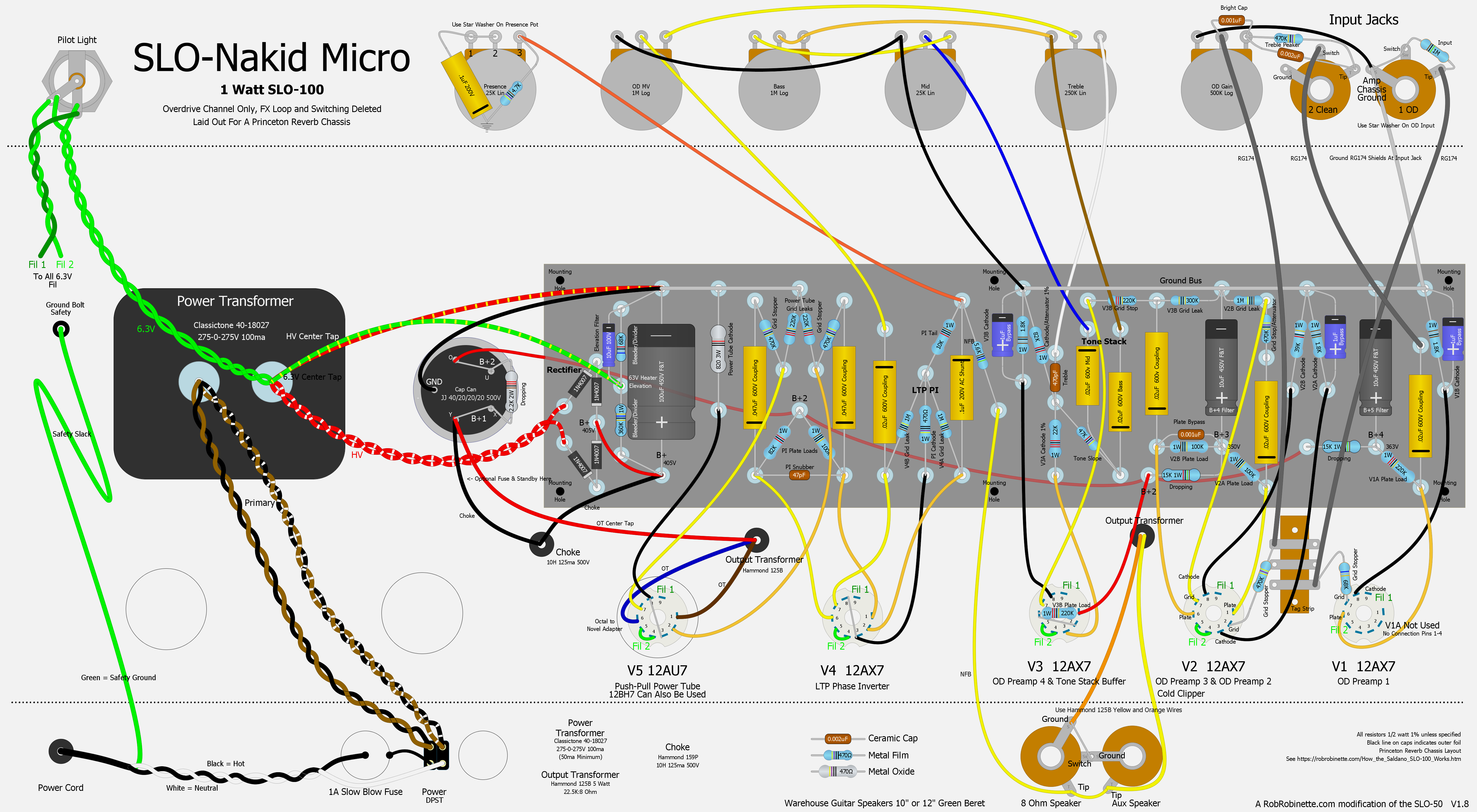
Power Transformer wire colors match the Classictone 40-18027 using the 120v primary. Red and white striped wires are the 275v secondaries. The cap can Y (40uF) and X (20uF) terminals are jumpered for 60uF 500v of B+1 (power tube plates) filtering. The U (20uF) and O (20uF) terminals are jumpered for 40uF 500v of B+2 (V3 & V4) filtering. Shrink tube, bundle, and tuck away the red 330v secondary wires. Click the image to see the high resolution layout, download the pdf here and download the DIYLC file here.
Bill of Materials
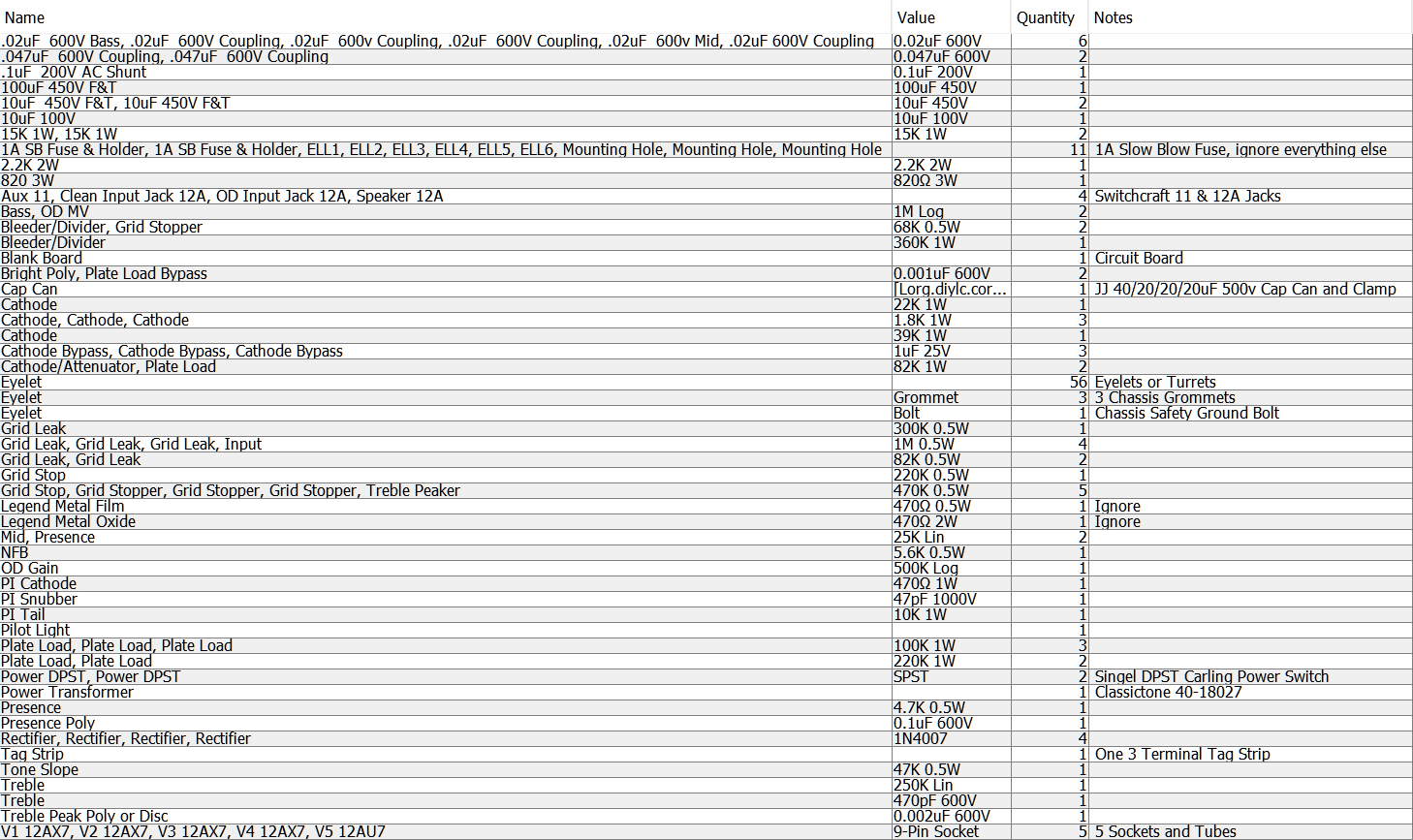
You'll also need a Princeton Reverb chassis, cab, speaker, power cord, wire, output transformer and choke. The 40/20/20/20uF 500v JJ cap can and mounting clamp came from Mojotone.com.
I recommend the use of a Princeton Reverb chassis.
You can upload the SLO-Nakid Micro DIYLC Hoffman board file to Hoffmanamps.com and Doug will make an eyelet or turret board for you. The empty board with eyelets or turrets installed is around $20 + shipping.
Power transformer minimum spec is 275-0-275v 50ma & 6.3v 2 amps. I recommended the Classictone 40-18027. It is made for the Princeton Reverb chassis and has an extra 275-0-275v secondary which is perfect for the SLO-Nakid Micro.
Classictone 40-18027 Power Transformer Wiring & Specs
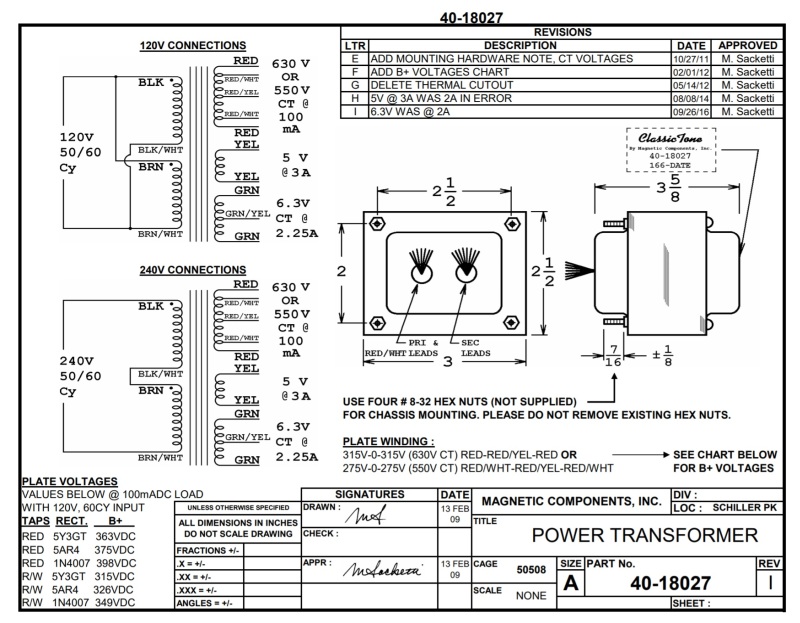
Note the 120v and 240v primary options. For 120v mains voltage we connect the Black & Brown wires together at the power switch and we connect the Black/White & Brown/White wires to the power switch or power cord neutral (see layout above). For 240v mains we join just the Black/White and Brown wires. We'll connect the Red/White 550v high voltage wires to the rectifier. Shrink-tube the two unused red wires so they cannot touch each other or anything else.
Output transformer specs are 22.5k:8 ohms push-pull. I recommend the Hammond 125B 5 watt. Output impedance is very flexible with 22.5k:8 using secondary wires 2 & 4 (orange & yellow). This impedance is optimized for the 12AU7 but will work for both the 12AU7 and 12BH7 power tubes. If you plan to use the higher power 12BH7 exclusively then an output impedance of 12.8k:8 using secondary wires 4 & 6 (yellow and white) will give more output power and slightly better tone. If you plan to use both the 12AU7 and 12BH7 then I recommend you split the difference between them at 17.6k:8 using wires 3 & 5 (green and violet). Note that we do not use the black (wire 1) secondary wire. I purchased my Hammond 125B from Mouser.com.
Hammond 125B Output Transformer Wiring & Specs
We do not use the Black secondary wire.
Choke minimum spec is 10H 50ma 450v. I recommend the Hammond 159P 10H 125ma 500v or Classictone 10H 100ma chokes.
Soldano amps usually sound great with Marshall style green back speakers. I'm a fan of the Warehouse Speakers Green Beret in 10 or 12 inch size. A standard Princeton Reverb cab will accommodate most 12 inch speakers including the Green Beret.
References
RCA Corporation, RCA Receiving Tube Manual, RC30.
Merlin Blencowe, Designing Tube Preamps for Guitar and Bass, 2nd Edition.
Merlin Blencowe, Designing High-Fidelity Tube Preamps
Morgan Jones, Valve Amplifiers, 4th Edition.
Richard Kuehnel, Circuit Analysis of a Legendary Tube Amplifier: The Fender Bassman 5F6-A, 3rd Edition.
Richard Kuehnel, Vacuum Tube Circuit Design: Guitar Amplifier Preamps, 2nd Edition.
Richard Kuehnel, Vacuum Tube Circuit Design: Guitar Amplifier Power Amps
Robert C. Megantz, Design and Construction of Tube Guitar Amplifiers
Neumann & Irving, Guitar Amplifier Overdrive, A Visual Tour It's fairly technical but it's the only book written specifically about guitar amplifier overdrive. It includes many graphs to help make the material easier to understand.
T.E. Rutt, Vacuum Tube Triode Nonlinearity as Part of The Electric Guitar Sound
[ How the 5E3 Deluxe Works ] [ Deluxe Models ] [ DRRI & 68 CDR Mods ] [ Amp Troubleshooting ] [ My 5E3 Build ] [ Spice Analysis ] [ The Trainwreck Pages ] [ Fender Input Jacks ] [ B9A Prototype Boards ]