[ How Amps Work ] [ Overdrive ] [ 5E3 Mods ] [ 5F6A Mods ] [ AB763 Mods ]
The Trainwreck Pages
I really like Ken Fischer's article, The Trainwreck Pages, so I spent a crap load of time putting the original poor quality scanned PDF file through optical character recognition (OCR) and a bunch of editing to create high quality versions of his article. The html version is here on this page but you can also download these versions:
Download the Trainwreck Microsoft Word DOC file
Download the Trainwreck Libre Office Open Document Format ODT file
Download the cleaned up and searchable Trainwreck PDF file
[Rob adds: I have added comments below to The Trainwreck Pages and put them in brackets and Italics like this so you can tell what is not original "The Trainwreck Pages" content. This webpage is available in .pdf form: The Trainwreck Pages by Ken Fischer with additional info by Rob Robinette.pdf]
WARNING: A tube amplifier chassis contains lethal high voltage even when unplugged--sometimes over 700 volts AC and 500 volts DC. If you have not been trained to work with high voltage then have an amp technician service your amp. Never touch the amplifier chassis with one hand while probing with the other hand because a lethal shock can run between your arms through your heart. Use just one hand when working on a powered amp. See more tube amplifier safety info here.
The Trainwreck Pages
by KEN FISCHER
![]()
Trainwreck would like to thank the following individuals who participated in the realization of this article:
Phil Lipman, Pam Lipman, Adam Apostolos, Sue Melkisethian, Steve Melkisethian
EXECUTIVE EDITOR: ESTA FISCHER
WARNING!
WARNING: The following amplifier modifications are intended for use by qualified personnel only. Guitar amplifiers contain LETHAL voltages. Even unplugged filter capacitors can store enough voltage to do permanent harm or be lethal.
DISCLAIMER: Trainwreck cannot warranty the suitability of any modifications. The use of any of these modifications is done entirely at your own risk and Trainwreck will assume no liability for any damages caused by such modifications.
TRAINWRECK IS NOT RESPONSIBLE for any misprints, typo errors or printing mistakes which may cause damage to people or equipment.
CAUTION: Unplug your amp before accessing any AC fuses. This will eliminate the possibility of an AC shock.
CAUTION: Certain amplifiers may have an HT (HIGH TENSION or HIGH VOLTAGE) fuse. Even when unplugged these fuse holders may contain high voltages. Use caution when changing the HT fuse. NEVER touch the metal end of the HT fuse with your bare fingers!
CAUTION: Tubes in amplifiers tend to get hot during operation. When changing tubes be sure to give tubes a proper cool-down period. To remove tubes grab the tube gently. Rock the tube in a circular motion while gently pulling it out. Be careful not to crush the tube which is made of glass and may cut your fingers.
WARNING: Never operate a tube amplifier without a suitable load; that is a speaker or dummy load.
Page 19
The Trainwreck Pages
HOW A GUITAR AMPLIFIER WORKS
After years of repairing, modifying and building amplifiers, Trainwreck has often been asked to explain the basic operation of guitar amps. The following section is intended to help those who are not experienced techs but who are interested in how an amplifier works. The example we have used is either a 50 or 100 watt Marshall tube amp with a Master Volume.
In this section we will try to shed some light on the following topics: AC, DC, voltage, current, power and wattage. These subjects can be very confusing and we will attempt to explain them as clearly as possible.
VOLTAGE is electrical pressure. You can think of it as the speed at which electricity flows. Using a car as an analogy, you can picture that a car going 10 MPH is low voltage and a car going 120 MPH is high voltage.
CURRENT is the quantity of electrons flowing past a certain point. This can be seen as analogous to the size of a car. A Volkswagen Beetle can be seen as a low current vehicle whereas an eighteen wheel truck would be a high current vehicle.
WATTAGE OR POWER is the combination of the voltage and the current. The formula for calculating wattage is to multiply the voltage by the current. That gives you total power. For example, the Volkswagen Beetle going 50 MPH hitting another vehicle would impart a certain amount of power. The eighteen wheel truck traveling at the same 50 MPH would impart far more power were it to hit another vehicle.
AC VERSUS DC: Electrical voltages have what is called a polarity. The most obvious example of polarity is the positive and negative terminals we see on batteries. The battery represents a DC voltage source and all the electrons in it flow from negative to positive terminals in one direction. In AC, or alternating current, the terminals alternate polarity. This reversal of polarity occurs sixty times per second in the standard US. household electrical system. This is what is called a "60 cycle current" (60 Hertz or Hz).
In audio this principle applies to a concept called frequency. For instance, when you pluck the 'A' string on your guitar the string vibrates back and forth 110 times per second (110Hz). The magnetic field of the guitar pickup is disturbed 110 times per second so an alternating voltage of 110 alternations per second is generated in the pickup.
The 'A' string also vibrates the air 110 times per second (that's how you hear the sound of the guitar acoustically). The air vibrates and alternately compresses and rarefies as the string vibrates. It vibrates your ear drum and you hear the tone.
Now we have established that the guitar develops an AC signal voltage. The strings vibration disrupts a magnetic field generating a voltage out of your pickup which is fed into the amp. The amps job is to make the speaker vibrate via an AC signal to reproduce this sound at the desired level.
Page 20
The Trainwreck Pages
The power supply section of the amp is the first section we will deal with. There are several different relevant voltages which are part of its operation. One voltage, called a "filament" or "heater" voltage, is the voltage that makes the orange glow inside the tube. This filament heats up an element called a "cathode" which is simply a metal cylinder coated with a substance which gives off electrons.
Other parts of the tube require positive voltages to attract the electrons. These voltages are much higher. The power transformer in your guitar amp converts the 120 volts (or 220-240 in Europe) to the VARIOUS voltages needed in the amp. For example, 6.3 volts are needed to heat the filaments in the tubes. The plate element in the tubes need several hundred volts for proper operation.
A transformer has a primary winding and several secondary windings. The ratios of the windings determine the amount of voltage produced. The signal coming through on the secondary windings is an AC voltage; aside from the filaments, every other required voltage in the amplifier is a DC voltage. Another circuit is called a "rectifier" circuit. It is either a tube or a solid state device which allows the electricity to flow only in one direction. It also stops the electricity from flowing in the reverse direction and therefore converts the alternating current to a current that is going in one direction, DC.
However this voltage will be fluctuating 120 times per second and to smooth out the fluctuations a device called an "electrolytic" capacitor, also referred to as a "power filter" or "filter cap", is used. This device is similar to a battery in that it stores electricity so that during the valleys between the pulses, the stored electricity keeps the current flowing in a smooth, orderly fashion. A SIGN OF A BAD POWER FILTER, WHEN IT DOES NOT ALLOW THE ELECTRICITY TO FLOW IN A SMOOTH, SOLID FASHION, IS A LOUD HUM.
THE PREAMP: The signal from the guitar is applied to an element called the "grid" of the preamp tube. The cathode of this tube gives off electrons and the plate of this tube, which is connected to a high voltage source, is attracting the electrons at a very high rate. The grid, which sits between the cathode and plate, acts as a valve or a control. The cathode in the tube is giving off electrons while the plate is attracting them at a high rate. In between you have the control grid to which the AC signal is applied. This is sort of an electronic gate which can be opened and closed by the amount of voltage on it. An analogy for this would be the faucet in your sink. If you turn the faucet on full and try to stop the flow by putting your finger over the end of the faucet, you will find it impossible. But with a little gentle pressure on the on-off valve you can easily control the flow of the faucet. This is how a tube amplifies. A very small voltage differential applied to the grid controls a very large voltage differential on the plate of the tube.
This is what is known as a "gain stage". The gain stage can multiply the signal being applied to it many times over.
Page 21
The Trainwreck Pages
In this Marshall amp, after the initial gain or preamp stage, there is inserted a control known as a "preamp volume" or "gain volume". There is another important circuit which we have to understand if we are to comprehend the workings of guitar amplifiers. It is called a "voltage divider".
Essentially, what is happening inside this "volume", "gain", or "preamp" control is that there is a carbon strip which has a resistance. Signal voltage is applied at one end of the strip from the preamp stage and the other end of the strip is connected to a point of zero voltage.
Because this strip has a property called "resistance" (an opposition to the flow of electricity, which slows the electrons down, therefore reducing voltage over its entire length) we can install a third element in this control.
This is the element that you use as you turn the shaft of the control pot. This element slides along the carbon granular path and allows you to select any voltage you want, anywhere between the full voltage or no voltage at all. As the slider goes down the carbon path toward ground, the less voltage you get. By selecting a point on the carbon path, you can choose the voltage and hence the gain and volume of the sound.
In a Marshall amp we continue on to two more gain stages. These continue to build voltage up to the point where we can institute OVERDRIVE. Before we discuss overdrive (or distortion) it is essential that we describe the fourth stage of the Marshall amp. The fourth stage is the tube setup and operation called the cathode follower which basically is used to convert the high impedance signal coming from the previous three gain stages to a low impedance signal to drive the tone control circuitry. A cathode follower has no gain at all.
The next circuit we run into on this Marshall are tone-shaping circuits. Basically the tone shaping is an arrangement of various values of capacitors and resistors that select certain ranges of frequencies and sends them off to a voltage divider; the bass, treble and mid range controls. These controls work on the same principle as the volume or gain control previously discussed except that they work on the volume of only certain frequencies. Therefore when you turn the control you affect the volume of a certain frequency and effect the overall tonal balance of the amplifier.
Page 22
The Trainwreck Pages
THE POWER AMP: After these three tone controls comes yet another voltage divider called the master volume. This selects the amount of voltage fed into the power section of the amp and thus effects the overall power generated by the amplifier. This control also affects the amount of distortion in combination with the gain or first voltage divider by the following principle: if you turn up the first voltage divider and therefore increase the amplification factor, by feeding more voltage into the later gain stages the later gain stages will eventually reach a point called "clipping". Clipping occurs when the voltage signal being presented to that particular tube stage exceeds the tubes ability to amplify it. What happens at this point is that the tube amplifies as much as it can and then abruptly stops, chopping off part of the signal. This distorts the signal and causes the tube to generate many harmonics. By increasing the preamp volume and reducing the master volume, we have a tendency to make the later stages of the preamp clip more and more severely thereby generating more and more distortion. This distortion is distinct from output stage clipping which is a type of distortion induced when the output stage delivers all the power it can and is pushed beyond its limits. It will also clip with a different sonic character.
From the master volume the signal gets fed into a circuit known as the "phase inverter" or "phase splitter". Essentially the function of this stage in the amp is to produce a mirror image voltage of opposite polarity, plus to provide drive voltage to the output tubes. This is necessary for the operation of the output stage which is in a configuration known as "push-pull". One half of the output stage receives a negative signal and one half receives a positive signal, so that the signal is being effectively pushed and pulled through the output stage at the same time. The analogy to this would be two people behind your car pushing and two people in front of your car pulling with ropes. It is a more effective set up than having just two people pulling or just two people pushing. This push-pull operation gets traded back and forth between the output tubes to develop the output power. In order for one set of tubes to push and the other to pull, they have to receive the signal in the right direction which is the job of the phase inverter.
The last device is the output transformer which has essentially two functions: one is to block DC voltage from being applied to the loudspeakers. Speakers do not work on DC voltages and since such DC voltage applied to the voice coils would have very negative effects, the output transformer BLOCKS DC and will not allow it to flow into the speaker. Also it converts the relatively high voltage/high impedance operation of the tubes to a lower voltage/lower impedance signal which matches the impedance of the speaker. Therefore it also functions as a matching device to the speakers.
There is one other circuit called the negative feedback loop which comes from the secondary or speaker side of the output transformer. It feeds a portion of the signal back into the amplifier in REVERSE (negative) polarity. The feedback loop goes from the output transformer stage and is fed back into the phase inverter stage. This helps the amp reduce distortion in its clean tone and tighten the overdrive tone.
There is one other control in the Marshall amp called the Presence control. This control increases the gain of the higher frequencies generating a brighter tone and more 'sizzle' in the distortion. Turning up the Presence knob actually defeats the effect of the aforementioned negative feedback loop in the higher frequencies!
Page 23
The Trainwreck Pages
CLASS A AMPLIFIERS
There has been a lot of confusion among guitarists and technicians about what constitutes a Class A output stage in a guitar amplifier. Many people assume that all amplifiers with cathode bias output stages are Class A and all amps with fixed output stages are Class AB1. Either type of bias circuit does not in fact automatically mean that the amp in question has either Class A or Class AB1 operation. The definition of Class A operation is that the output tube conducts signal for 360 degrees (or the full signal swing). This automatically means that any single-ended amp (that is, any amp with just one output tube such as the Fender Champ) must operate in Class A or they would clip even on the clean signals.
Class AB1 operation is when the signal flows for at least 180 degrees of signal swing but less than 360 degrees of signal swing. This is commonly used in "push-pull" circuitry because the phase inverter supplies only 180 degrees of signal swing to each side of the output stage. The two sides of the output stage combine their 180 degree signal swings to make the full 360 degree signal swing. A Class AB1 amp can be converted to a Class A amplifier by adjusting the bias so that the tube will conduct during the full 360 degree signal swing.
However this is often impractical, as lowering the grid bias voltage without lowering the plate voltage will cause the tube to exceed its current handling ratings in some amplifiers. It may also cause the output transformer to saturate on DC current which will block it from producing the AC signal current and it may exceed the current supplying capability of the power supply resulting in overheating (burnt transformers) and other components.
Push-pull Class A amps, such as the Vox AC-30 may be easily biased into Class AB1 operation. Basically the only modification necessary to accomplish this is to increase the value of the bias resistor to achieve Class AB1 operation. A common misconception is that Class A operation is always notoriously inefficient but amplifiers such as the Vox AC-30 and the Trainwreck Liverpool 30 are relatively efficient and lose only a few watts compared to Class AB1 operation.
This inaccurate reputation stems from a particular type of Class A operation used by audiophiles, the CLASS A TRIODE. The power output tubes used in amplifiers are five-element tubes called "pentodes". However the screen grids in these tubes are hooked directly to the plate and operate as a three element tube or “triode". This class of operation dramatically increases the screen current, requiring that the voltages be substantially reduced, hence the inefficiency. These audiophile amps are actually fixed bias amplifiers rather than cathode biased.
Most Class A guitar amplifiers are cathode biased. The way in which we arrive
at the correct bias voltage for a fixed bias Class A amp is to raise the grid
bias voltage to the exact point of tube cutoff and then divide that voltage in
half. This way the tube will reach clipping and zero bias with exactly the same
voltages, just in the opposite directions of opposite polarities. If the
tube is operated on an AC filament line, then one half the filament voltage must
be added to the bias voltage to compensate for the swing of the filament voltage.
[Rob adds: sentence applies only to special, rare tubes with directly heated cathodes]
Page 24
The Trainwreck Pages
ADVANTAGES AND DISADVANTAGES OF CLASS A OPERATION
In a typical "push-pull" amp, one of the characteristics most guitarists want to avoid is the type of distortion known as "crossover notch" distortion. This distortion has a harsh, non-musical quality to it and tends to appear when a tube amp is over biased or “cold” biased and the amp tone is characteristically very weak, but also very "broken up".
The advantage of Class A operation is that it minimizes crossover notch distortion under severe overdrive conditions. Therefore a smoother, more musical distortion tone is produced. However many heavy metal players prefer the tone of a fixed bias CLASS AB1 amplifier, such as a Marshall, for its aggressive, crunchy tone. Blues and fusion players and players who prefer a less aggressive tone often prefer a cathode biased Class A amplifier. A fixed bias Class A amplifier has a tone which falls about halfway in between these. Mesa Boogie uses fixed bias Class A in their Simulclass amps for example.
AMPLIFIER BIASING
WARNING: The Trainwreck method of biasing an amplifier requires that you work with a "live" amp at the points which contain the most LETHAL voltages! ! ! If you are not thoroughly familiar with the safety precautions for working with live amps at high voltages, Trainwreck recommends having a trained technician do the biasing work on your amplifier.
1. There are two systems most commonly used to bias the output stage of a guitar amp. One system is called "cathode bias". In this system a resistor is connected in series from the cathode to ground. This type of biasing system adjusts itself automatically by the current draw of the output tubes. It requires no adjustment.
2. The other common method of biasing an amp is called "fixed bias". In this method a negative voltage is applied to the control grid of the output tube to adjust the tube to its optimum operating range. This adjustment might be seen as comparable to the setting of the level of idle in a car. If you set the idle level too slow the car will hesitate, acceleration might be too sluggish and the car could possibly stall out. If you adjust the idle too high the engine will be racing and may overheat or damage the transmission.
The same holds true for the output stage of a guitar amplifier. An under biased or “hot” biased amp can destroy both output tubes and output transformers. Hot biased amps characteristically sound muddy and tend to hum abnormally. An over biased or “cold” biased amp will not play clean under most circumstances. Its clean channel will sound fuzzy and thin and its distortion tone will be weak and thin. Certain cold biased amps have a tendency for ARCING (just like an arc welding rig!) across the output sockets!
HOW TO ADJUST THE BIAS ON A FIXED BIAS AMP
There is an incorrect, yet commonly recommended method for biasing amps being circulated by many sources, including the manufacturers of tubes and amplifiers. This method instructs the repairman to connect the amp to a 'dummy load', attach it to an oscilloscope and put a signal into the amp with a signal generator. Then the instructions are to bring the amp to full power, raise the grid bias voltage until a crossover notch appears and lower the bias voltage back until the crossover notch just disappears.
Page 25
The Trainwreck Pages
The problems with this method of adjusting the bias are plentiful! Number one, this method is extremely inaccurate and if you repeat this operation three or four times and measure the bias voltage, each time you will have a different bias voltage! The point at which the crossover notch disappears is a very subjective concept and bound to be a highly unreliable method for gauging an adjustment such as this one. The second major flaw with this method is that it leaves the tubes cold biased and in a few months when the tubes age the crossover notch will reappear and in this cold biased condition the amp will sound weak.
WARNING!!! TRAINWRECK DOES NOT RECOMMEND THE ABOVE METHOD FOR BIASING AN AMP! IT IS INTERESTING TO NOTE THAT NO HIGH-END AUDIOPHILE AMPLIFIER USING VACUUM TUBES RECOMMENDS THIS METHOD OF BIASING! INSTEAD, THEY UTILIZE THE SAME BIASING TECHNIQUE FAVORED BY TRAINWRECK CIRCUITS!
There is another system for biasing an amp using fixed bias called THE VOLTAGE MEASUREMENT SYSTEM. This method requires measuring the bias voltage on the tube grid (usually Pin 5 on most common output tubes) and adjusting it to a specified voltage. This method does have an advantage over the CROSSOVER NOTCH DISTORTION METHOD, but is still not the most accurate method of biasing an amp.
Trainwreck's preferred biasing system is called the MEASURED CURRENT BIASING SYSTEM. This method actually measures the current flow through the output tubes and is thus an extremely accurate measurement as compared to either the Crossover Notch Distortion or Voltage Measurement System.
This method also makes it very easy to repeat exactly the same setting from one set of tubes to another and allows for a very consistent tone when changing tubes. This method also allows you to adjust the tubes within the safe operating range to achieve the desired tone. For instance, with an amp with a very high bias the tone may tend to be crunchy but thinner.
With a lower grid bias voltage and the increased current the same amp might have a beefier tone and more gain. The tradeoff is that you may have to sacrifice a certain amount of crunch. By using the CURRENT METHOD you are able to fine tune the amp to your particular tone and have it remain consistent from one set of tubes to another (especially when using "matched" sets of tubes).
TWO METHODS FOR MEASURING CURRENT ΙΝ ΤΗΕ ΟUΤΡUΤ SΤΑGΕ
WARNING!!! Amplifier must be on for all tests detailed below and must be connected to a speaker or a dummy load with no signal being applied to the input to measure the current.
1.) One method involves unsoldering the center tap of the output transformer and putting a current meter in series with the tap to the voltage source. This measures the current of all of your output tubes simultaneously but also includes screen grid current and preamp tube current. Using this method, you can determine an estimate of current for each individual output tube by taking the total amount of current and dividing it by the number of output tubes. Therefore, if you have two output tubes, the single tube current is equal to half the total output tube current. If you have six output tubes, the single tube current would be one-sixth the total output tube current.
Page 26
The Trainwreck Pages
Using this method on a typical amplifier (such as a Fender, Mesa, Marshall, etc....) the safe operational range per tube is generally from 10-40 milliamps (a milliamp is one thousandth of an amp) per tube. For example, using a 100 watt Marshall with 4 power tubes as an example, 4 times 10 is 40 and the minimum current you would adjust for would be 40 milliamps. Four times 40 is 160 and 160 milliamps would be the maximum current. WITHIN THOSE PARAMETERS, ANY CURRENT THAT YOU FIND PRODUCES THE TONE YOU DESIRE IS THE "CORRECT" SETTING!
Conventional amplifier designs using fixed bias generally run 10-40 milliamperes per tube. Unsoldering the center tap and putting a meter in series can be extremely inconvenient on some amps. Trainwreck uses another system for measuring current, which does not require any wires to be disconnected in the amplifier.
Instead, the positive lead of the current meter will connect to the point of the center tap of the output transformer and the negative lead of the current meter should be connected to the plate pin of one of the output tubes. The plate pin is often Pin 3 in many tubes. Examples of tubes which would commonly utilize Pin 3: 6L6, KT66, KT 77, KT88, 5881, 6550, 6W6, EL34, 60A7. Some tubes, such as the EL84 (AC-30), 7591, 7027A, 7868 have the plate on a different pin.
However as we are measuring only ½ of the primary we will only be measuring the current for half the "push-pull" output. This method is accurate primarily because of the very low resistance of the meter which effectively shunts the winding of the output transformer and allows the total current to flow through the meter. Please bear in mind however that you are only measuring one half the output stage current. For example, if you want to set a 4 output tube amp to 30 milliamps per tube, first multiply 4 tubes times 30 milliamps to equal 120 milliamps total. Now since this method only measures one half of the total current you would adjust the bias until the meter reads 60 milliamps (one half of the 120 milliamp total).
Some amplifiers are equipped with a variable bias adjustment which may be turned with a screwdriver to obtain the proper operating range. Some amps have fixed resistors and values of resistors must be substituted until the proper bias current is observed.
CAUTION: This system of biasing amps will not work for every make! For instance, Music Man, Hiwatt 200 and 400 have different systems for biasing. The Ampeg SVT has a built-in biasing system where you measure a voltage on the front panel through access terminals and it measures a voltage which is dependent on bias current.
CBS Fender amps often have a different biasing system. In the late '60s CBS used a biasing system which adjusted the balance of bias between the two output tubes. These amps are easy to detect as the bias voltage on each half of the output tubes is not necessarily equal.
Page 27
The Trainwreck Pages
In other words, the voltage on Pin 5 on one output tube and Pin 5 on the other output tube may actually be different. Any Fender amp which has a bias adjustment on the back panel is an amp of this variety. The way the bias is adjusted on these particular amps is to turn the control until you observe the minimum amount of hum in the speakers. This is a poor system as the bias tends to drift and change as the amp warms up. We recommend that these amps be converted to the earlier Fender system which allows you to adjust the bias current. This modification combined with the use of balanced output tubes will generally cancel out any problematic hum.
CAUTION: DO NOT ATTEMPT TO ADJUST FENDER AMPS WITH A BALANCE TYPE BIAS SYSTEM BY THE CURRENT METHOD ! ! ! ! !
BIASING THE TRAINWRECK AMPLIFIER
The Trainwreck Circuits Liverpool 30 amp employs a cathode biasing system which requires no adjustment. Four EL-84 (VOX STYLE) output tubes are used to power the output section. The Trainwreck Express amp is unique in that it is capable of using either two 6V6 (typical of Fender Princetons, Deluxes, etc.) or EL-34 (generally associated with Marshall amps) output tubes. They can be switched without adjusting the amp. Because of this feature a Trainwreck Express amp should not be biased by current. Instead it is recommended that biasing be done by the Voltage Method by setting the grid voltage.
The correct bias voltage for a Trainwreck Express amp in operating position using a digital multimeter is -30 volts on Pin 5 of the output tube, which may be adjusted by using the variable adjuster inside the chassis. Normally this adjustment will never have to be made. A special process at Trainwreck manufacturing headquarters insures that there will be little need for bias adjustment for many years!
CBS FENDER AMPLIFIERS: On January 5, 1965 CBS became the official owners of the Fender Musical Instruments group (formerly known as the FENDER ELECTRIC INSTRUMENT CO.). Although in 1965 they did not start changing circuit designs, eventually they started changing circuits in all of their amplifiers. These legendary changes were not for the better. There was an eight month period of trying to combine cathode and fixed bias technologies in one product! These units were a dismal failure and among the worst sounding of the CBS Fender amplifiers. Unfortunately CBS never returned to their production of pre-CBS circuitry however the amps made just after CBS took over are easily converted back to the coveted pre-CBS Fender specifications.
Obtain a copy of AA763 or AB763 schematic for your Deluxe, Tremolux, Super, Twin, Showman, Bandmaster, etc. Following the schematic, it is possible to remove the dreaded CBS circuitry to match the pre-CBS schematic. If modified correctly your amp should have that pre-CBS Fender tone.
Page 28
The Trainwreck Pages
CBS FENDER AMPS (CONT.)
It is also important to note that CBS routed wires differently in the amplifier and started having a problem with a phenomena called "parasitic oscillation". The aural manifestation of this problem was a sound not unlike the buzz of an insect which would appear on top of the clean note produced by the guitar and amplifier. To eliminate this problem Fender added a .002uF (micro Farad or μF) capacitor across the output tubes to shunt this oscillation to ground. Unfortunately most amplifiers which were produced with the .002uF capacitors across the tube circuit require them to be there even after the conversion back to pre-CBS specs.
The only way to eliminate this problem is to use the original wiring layout: As you would require a pre-CBS amp to copy the layout from this operation is not particularly practical and we don't recommend it.
Later Fender increased the output of their amplifiers in another attempt to keep up with the times. Super Reverbs became 70 watts, Twin Reverbs and Bassmans were increased to 135 watts. These amplifiers can never be brought back to the original pre-CBS tone due to their larger transformers.
PICKUP TESTING FOR VINTAGE GUITAR OWNERS (HOW TO TELL IF A PICKUP IS OK WITHOUT REMOVING IT FROM THE GUITAR)
Our first premise is that anyone owning or rewiring vintage speaker cabinets or pickups should own or have access to a device known as a multimeter. This device measures voltage, current and resistance. Such a multimeter may be purchased at a very low cost at most electronics stores. We recommend that anyone purchasing a multimeter be sure to get one with a digital readout rather than a model with a swinging needle. The digital units are far easier to use.
With the popularity of vintage guitars we are finding that some unfortunate collectors have purchased guitars which function but contain open pickups. This occurs because a break in the wire in the middle of the pickup will allow the pickup to function because of capacitance effect but the tone is hardly vintage! A telltale sign of this syndrome is a harsh, shrill tone coming from the pickup and the fact that the tone control does not appear to work correctly. This is a particularly common problem with older Fender Telecaster bridge pickups and occasionally with Gibson P-90 'soap bar' pickups. It is a rare occurrence with humbuckers.
Your pickup may be very easily checked for continuity without removing it from the guitar through the output jack of the instrument. A ¼" phone plug should be inserted into the jack of the guitar, the multimeter is to be set on an appropriate resistance range and one lead of the meter is connected to the hot terminal and the other meter lead is connected to the ground terminal of the phone plug. The volume and tone control are to be turned all the way up.
Page 29
The Trainwreck Pages
PICKUP TESTING (CONT.)
The pickup resistance can be measured and should read slightly lower than it would outside of the guitar due to the parallel effect of the volume and tone pots.
Examples of typical readings for various pickups are as follows: #1). A Fender type pickup will typically read from 4,000-10,000 (4K-10K) ohms maximum.
If you find that your Fender-style pickup reads over 10,000 (10K) ohms, your pickup is probably either over wound or a non-vintage replacement (more winds = more resistance). Pickups reading over 20,000 (20K) ohms can be generally considered "open". These pickups are worthless!
#2). Humbuckers generally read somewhere between 6,000-18,000 (6K-18K) ohms.
WHEN PERFORMING THIS TEST, BE SURE TO REMEMBER TO USE THE GUITAR PICKUP SELECTOR TO TEST ALL OF THE PICKUPS INDIVIDUALLY!
Marshall SUPER BASS to SUPER LEAD Conversion
This modification applies to standard four-input 50, 100 and 200 watt models. Chassis should be removed and placed upside down (with transformer and tubes facing downwards). The back panel should be facing the technician and the control panel facing away from the technician. This will put the power tubes to the left and preamp tubes to the right of the technician.
STEP ONE: Locate first preamp tube (all the way to the right hand side). Locate pin 3 on the first preamp tube. Pin 3 is connected to an 820 ohm resistor with either a 250uF or 320uF capacitor. From Pin 3 jumping across the tube socket is a wire. Remove this jumper wire but leave the 820 ohm and 250uF capacitor connected to Pin 3. From Pin 8 run a wire to a 2.7K ½ watt resistor to ground. Run a .68uF capacitor to ground to Pin 8. This capacitor may be a low voltage type (typically 25V).
STEP TWO: Locate Pin 6. Pin 6 connects to a 100K ½ watt resistor. There is a .022uF (or 22nF or nano Farad) capacitor. Remove this capacitor and replace it with a .0022uF capacitor, sometimes labeled 2N2 (2.2nF). Locate the treble pot. From the right hand terminal of the treble pot a wire runs to the circuit board and connects to a 250pF (pico Farad) capacitor. Replace the 250pF with a 500pF capacitor. The opposite end of the 500pF capacitor connects to a 56K ½ watt resistor. The other end of that resistor connects to the .022uF capacitor which runs to the bass and mid controls. Change this 56K resistor to 33K. Locate the volume control for the first channel. Across the center and the right hand terminal (the wiper and the hot terminal) install a .005uF capacitor. Locate the third tube (the phase inverter) which is the third from the right. The plates on these tubes are PINS 1 and 6. Both Pin 1 and Pin 6 run to their individual capacitors. Replace the .1uF capacitors with .022uF capacitors. This completes the normal "SUPER BASS TO SUPER LEAD" modification.
On some Super Lead amplifiers (particularly the earlier ones) there was an additional .68uF capacitor used. Locate the second preamp tube. From Pin 3 a wire runs to an 820 ohm (sometimes this is a 1K) resistor to ground. Add from the same pin a .68uF capacitor to ground. This will add slight high end and slightly more distortion.
THE .68uF CAPACITORS AND THE .005uF CAPACITORS MAY BE OF A LOW VOLTAGE TYPE. ALL OTHER CAPS MUST HAVE A VOLTAGE RATING OF 400 VOLTS OR BETTER!
Page 30
The Trainwreck Pages
MODIFICATION FOR INCREASING OUTPUT TUBE RELIABILITY FOR MARSHALLS
PREFACE: Marshalls were originally intended to run on Mullard or Brimar brand EL-34 output tubes. Unfortunately the output tubes being manufactured throughout the world today cannot take the same stress as the original tubes.
A very simple modification for increasing tube life without altering the tone of the amplifier is to lower the value of the bias feed resistors in the output stage.
STEP ONE: Going to Pin 5 of each (or pair in the case of a 100 watter) output tubes there will be a pair of 220K resistors connected to the bias circuit. We want to reduce those 220K bias feed resistors to 100K. This will increase the longevity of your output tubes.
STEP TWO: In the case of the early 50 watt Marshalls, which did not include screen resistors, installing a screen resistor on each output tube will allow it to use modern tubes without instant self-destruction! This is accomplished by removing the wire from Pin 4, connecting one end of a 1000 OHM 5 watt resistor to Pin 4 and connecting the wire that previously went to Pin 4 to the remaining resistor wire.
Another way to achieve roughly the same result is to solder this resistor between Pin 4 and Pin 6 and connect the wire that previously went to Pin 4 to Pin 6. The primary negative impact of using a screen resistor is a slight reduction in power and a change of tone which may or may not be desirable. However when using the modern EL-34 tube this modification is almost a necessity as the average tube life can be as short as five minutes. If you do not wish to do this modification to your Marshall and you cannot find original Mullard or Brimar tubes you may use the American Phillips brand 6CA7 which is a large bottle type EL-34. These are available from many sources including MESA/BOOGIE, Groove Tubes, TNT, etc. This tube does not require the installation of the screen resistor as it can competently handle the screen current "as is".
BIAS INFO SUPPLIED WITH MARSHALL MATCHED TUBE SETS
Prior to packaging Marshall EL34M replacement tubes are subjected to a series of specially designed in-house test and selection procedures. These not only select the tubes to a band of parameters that have been shown to produce the optimum in terms of performance reliability and creating the genuine Marshall sound, but also subject the tubes to an abnormal check, in real world amplifier conditions, recreating the harsh tube situations found in a guitar amplifier. Unless your amplifier has been reworked or serviced since it left the Marshall factory then these tubes are a direct replacement without the need for rebiasing. If it has, or you are unsure, the bias should be checked and if necessary adjusted by a competent audio electronics engineer to the following figures:
50w JCM 800 MODELS –39 VOLTS
50w PRE JCM 800 –32 VOLTS
100w ALL AGE MODELS –42 VOLTS
When fitting these tubes to pre-JCM 800 50 watt models it should be checked that the amplifier is fitted with screen resistors. If not these should be fitted: 1 Kohm 5 watt being the required value. If not premature failure can arise.
When fitted to other makes of amplifier the bias should be set to the manufacturers specifications.
Genuine Marshall spares No: O/PV
Page 31
The Trainwreck Pages
MASTER VOLUME Mods For MARSHALLS: Four Types
Types 1, 2 and 3 master volume go after the phase inverter section. This type of modification is to be done to four-input Marshall amplifiers which are to remain four-input Marshalls and uses the extra gain stage of the phase inverter to achieve adequate distortion. The type 4 Master Volume is used directly after the preamp and before the phase inverter. That is the type of Master Volume used when adding a gain stage. It is the type of Master Volume which is "stock" in two-input Master Volume Marshalls straight from the factory. [Rob Robinette adds: The following master volume mods are not just for Marshall amps. They work perfectly fine in similar Fender and other brand amps. If your amp has a global negative feedback loop then the Type-1, 2 and 3 Master Volumes will sound a little funky at extremely low master volume settings--but this is only noticeable at really very low MV settings.]
Type 1 uses a double one meg audio taper pot and is the type used in certain old Marshall combos and certain other Marshall amps as a factory Master Volume. However this type of Master Volume has the unfortunate side effect of limiting the quality of the amplifiers original fully 'cranked' tone. If it is important to maintain the option of producing the original tone of the Marshall on '10' then this mod will not achieve your goals.
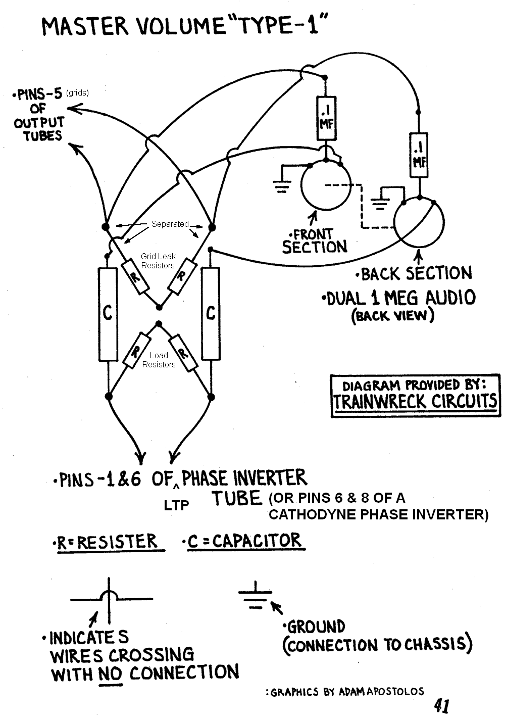
[Rob adds: The Master Volume Type-1 is overly complicated and I do not recommend it. The Type-1 inserts a dual 1MA pot (1 mega ohm audio or log, dual gang pot--1 shaft turns both pots together) between the phase inverter output coupling caps (C) and the power tubes' grid leak resistors (upper set of resistors). Note in the diagram above the capacitors and grid leak resistors have been separated. The pots function as simple volume controls (variable potentiometers). The 0.1uF caps attached to the master volume pot wipers are coupling caps that keep the power tube grid bias voltage out of the master volume pots.]
Types 2 and 3 both allow the amp to return to its original 'fully cranked' tone with the volume set to '10'. One circuit (which is a Trainwreck exclusive) uses a double 100K linear taper pot and the Type 3 uses a single 1 Meg audio taper pot and is the simplest style of Master Volume to install in a Marshall. However all three Master Volume circuits have distinctly different Sounds when using the Master Volume and the user should be aware of the tone he or she is shooting for in selecting a particular style of Master Volume.
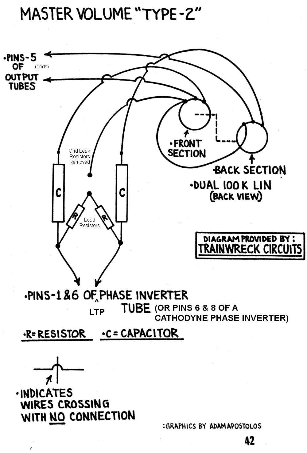
[Rob adds: The Master Volume Type-2 Is the most "transparent" and my recommended MV because at max volume the amp circuit is unchanged. The Type-2 simply replaces the power tubes' grid leak resistors (upper set of resistors) with a dual 100KL pot (100 kilohm linear pot, dual gang--1 shaft turns both pots together). The grid leak resistance does not change when the master volume is adjusted so there is no change in bias voltage on the power tube grids. Note in the diagram above the grid leak resistors have been removed (see the Type-1 diagram for comparison). The pots function as variable power tube grid leak resistors. The pots' left terminals are tied together and connected to the old junction of the original grid leak resistors. That junction is either tied to ground for cathode biased amps or to the bias power supply for fixed bias amps. If you are building a new amp I recommend installing this MV during the build. I recommend a 100KL dual gang pot when the original grid leak resistors are 100K. For amps with 220k grid leaks like most Fenders I recommend a dual gang 220KA pot like this. Another option is placing two 1.8M resistors in parallel with the 250KA dual gang pots. Solder the resistors across both pots--center terminal to input terminal (as shown below). This will improve the pot's taper and drop the pot's max resistance from 250k to 220k. The "Lar Mar" MV is simply a Type-2 MV using 2.2M resistors added to a 250KA dual gang pot. The 1.8M resistors reduce a 250K pot's total resistance to 220k and act as a safety path for the bias voltage in case the pot wiper fails.
Lar-Mar/Type-2 Master Volume in a 5F6A Bassman
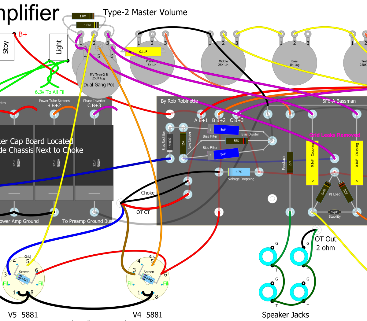
The 1.8M resistors on the Master Volume pot reduce the pot resistance to 220k and add a failsafe path for bias voltage.
Type-3 Master Volume
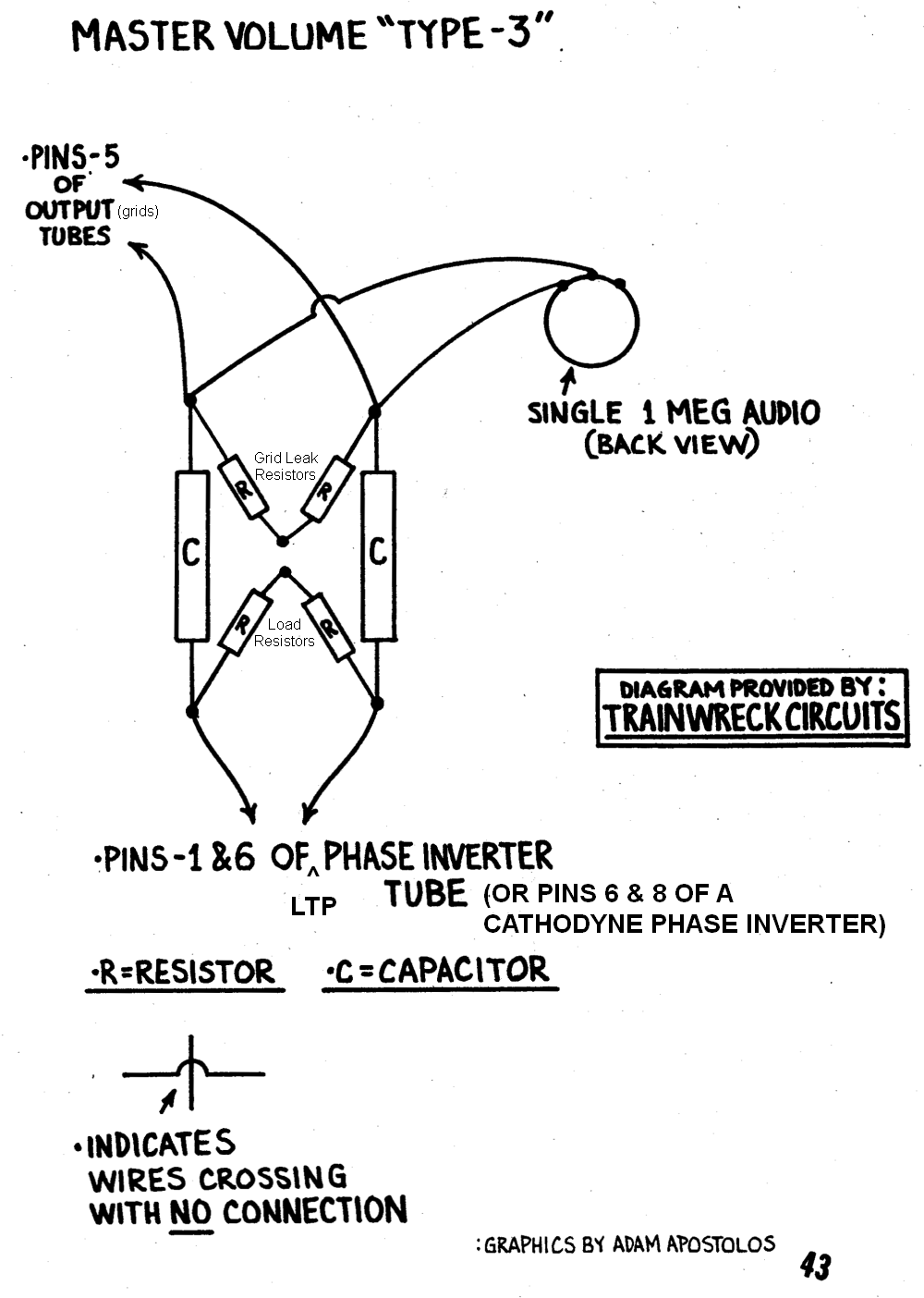
[Rob adds: The Master Volume Type-3 adds a 1MA pot that simply mixes the two mirror image audio streams from the phase inverter together. The two streams will cancel each other out. This master volume is very easy to try by simply alligator clipping in a 1MA pot. I installed this master volume in my 5F6A clone and I'm very happy with its performance.
If you are anal you can completely eliminate the Type-3 from the amp circuit by adding a switch to disconnect the circuit. Use a 1MA pot with a push-pull DPDT switch and wire one leg of the master volume through the switch so when the master volume knob is down the circuit is completely disconnected. Pull the knob up to activate the master volume. To do this you would run the wire from the pot wiper terminal to the upper left DPDT switch terminal, then run a wire from the middle left DPDT switch terminal to the circuit board's right grid leak resistor. The wire from the #1 (left) pot terminal would be wired as normal to the left grid leak resistor (see layout below).
Type-3 With MV ON/OFF Push-Pull Pot
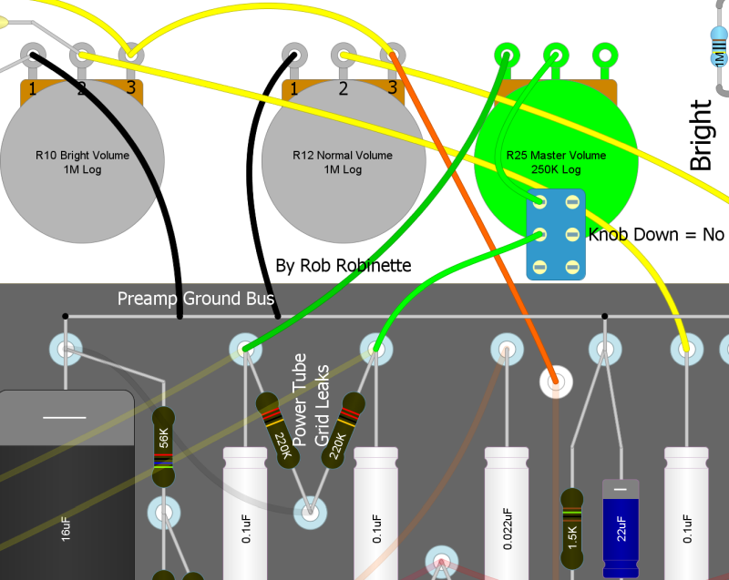
Master Volume knob Down = no master volume at all, Up = master volume on. This diagram shows a Fender 5E3 Deluxe but the wiring is the same for most amps.]
Vox Cut Control & Cut Control + Type-3 Master Volume
The Vox Cut Control connects the two power tube grids with a 220k audio pot and 4.7nF (.0047uF) capacitor to allow variable high end cut. In a push-pull amp the guitar audio signals on the two power tube grids are 180 degrees out of phase with one another so mixing them together nullifies the signal, kind of like mixing matter and antimatter. The capacitor limits the effect to high frequencies but if you jumper around the cap the pot becomes a Trainwreck Type-3 Master Volume.
I'm a big fan of this very late tone tweak because it pairs well with an early tone control or stack. Use the early tone control to get the overdrive tone and substance you want then use the Cut Control to fine tune the tone. The Cut Control affects only the power tubes.
Wire the cut pot as a variable resistor so that as you turn the knob up (clockwise) resistance increases. Up = more resistance = brighter tone.
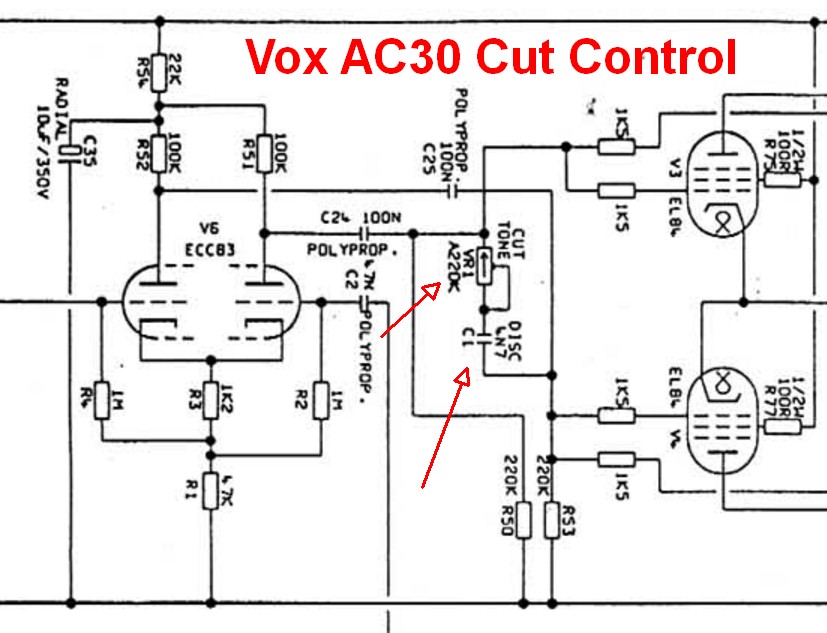
220KA or 250KA pot (audio pot wired as variable resistor) and .0047uF 200v cap connect the two phase inverter outputs.
Type-3 Master Volume + Cut Control Push-Pull Pot Mod
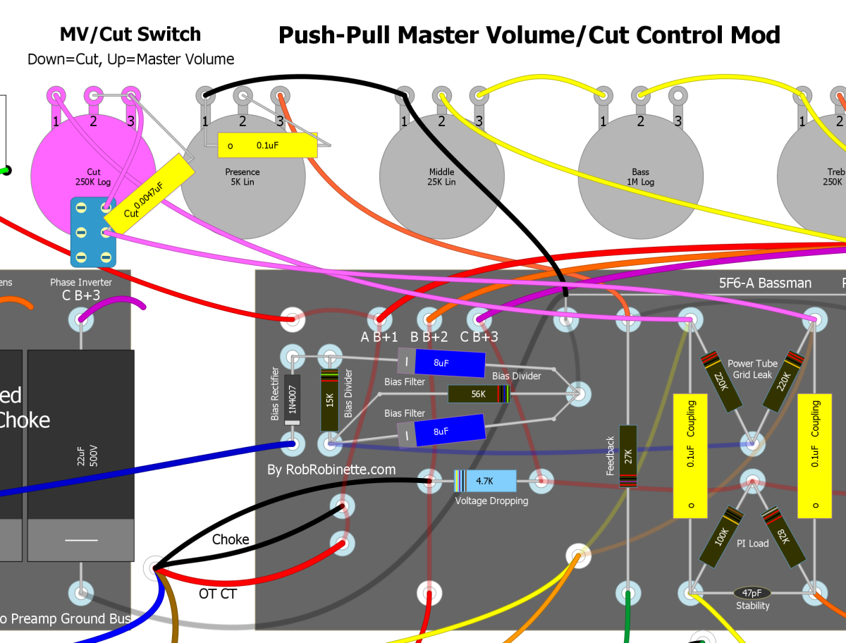
You can turn a Cut Control into a Trainwreck Type-3 Master Volume by simply jumpering around the Cut Cap. Use a 250KA push-pull pot and you can push the pot down for Cut Control or pull it up for Master Volume. Connect the "cut capacitor" from pot terminal #3 to the middle switch terminal.
Now back to The Trainwreck Pages original content]
Type 4 Master Volume which is used on the later Marshall amps tends to produce the more modern 'heavy metal', hard core tone. With the addition of an outboard overdrive unit, channel-jumping on four input Marshalls or the actual installation of an additional preamp stage will tend to produce the most distortion.
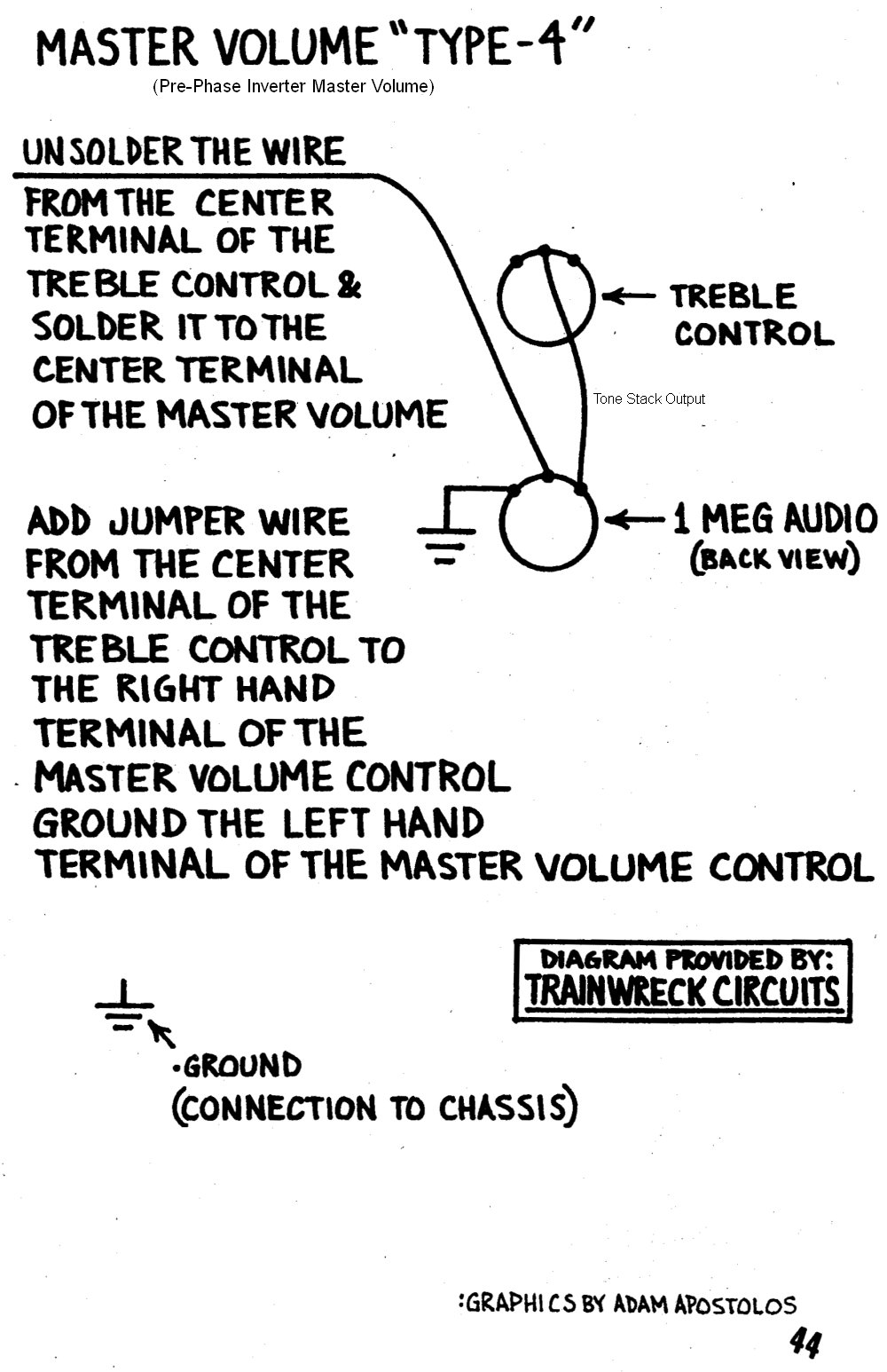
[Rob adds: The Master Volume Type-4 adds a 1MA pot that acts as a simple volume control immediately after the tone stack (the treble control wiper is the tone stack's output. While Master Volume Types 1, 2 and 3 are Post Phase Inverter Master Volumes (PPIMV), the Type-4 is a pre-phase inverter master volume because it is inserted before the phase inverter and therefore will control the amount of phase inverter and power tube distortion. The Type-4 works well with cathodyne phase inverters because the master volume can control their nasty sounding double-frequency overdrive distortion. When possible it is best to replace the amp's 1M grid leak resistor with the Type-4 1MA pot. By doing this the circuit is unchanged when the MV is set to max. See my 5E3 pre-phase inverter master volume mod for details.]
THE BEST
TUBE AMP
MADE TODAY
Page 32
The Trainwreck Pages
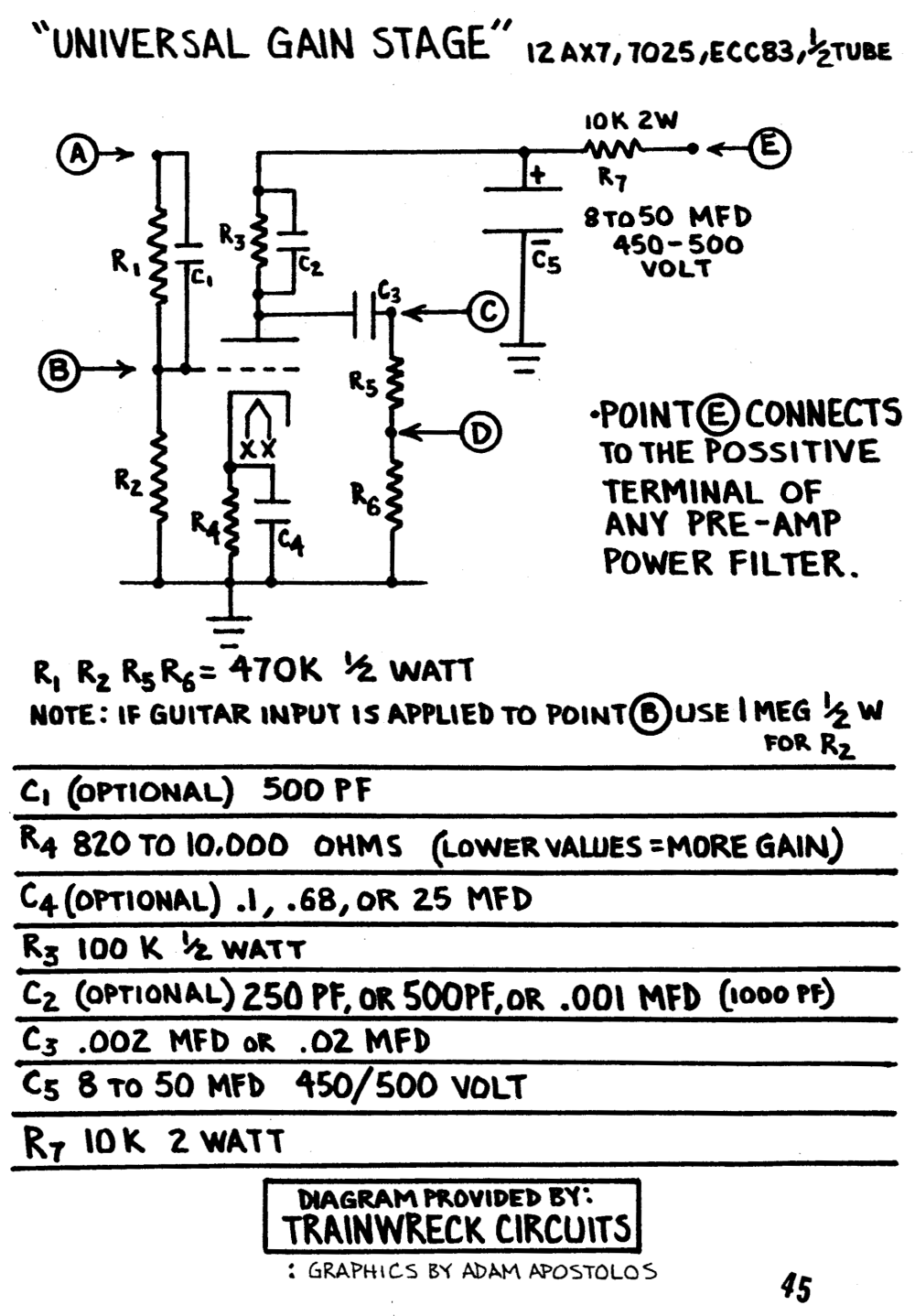
UNIVERSAL GAIN STAGE
Here's a gain stage you can use with a Fender, Marshall or almost any tube amp (see diagram at the end of these pages). The gain stage described here can be used as the input stage; the guitar goes directly into it for a boost before it goes into the amps normal circuitry. This gain stage can also be inserted between any points in the preamp of the amp you want to modify. For example, in a Marshall you would use this gain stage in either the first position as the very first preamp (the first thing the guitar signal "sees"), or you would use it in the second position AFTER the amp's first preamp; it would be inserted right after that point. Typically in a Fender this gain stage would be used all the way at the end of the preamp, after it has gone through the amplifier's entire preamp stages. In a Fender the last stage you would add would be this stage.
WARNING! THIS IS A VERY COMPLICATED PROJECT. IT REQUIRES A CERTAIN LEVEL OF EXPERTISE. IT IS VERY IMPORTANT IN USING AN EXTRA GAIN STAGE TO USE PROPER LEAD DRESS, TO USE SHIELDED WIRE WHERE NECESSARY TO KEEP THE AMP FROM OSCILLATING AND TOTALLY FREAKING OUT!
If you intend to use this circuit as a first gain stage then the guitar input would be connected to Point B on the diagram. The R-2 resistor would be a ONE MEG OHM ½ watt type. Resistor R-1 and capacitor C-1 would not be used if this gain stage is being used as the first stage in the amplifier.
If this is being used as the second stage in the amp, for instance as in a Marshall, then R-1 and C-1 WOULD be used. C-1 is optional. If you find the amp is too brilliant with C-1 in place then removing C-1 will reduce the treble response.
R-4, the cathode resistor, can be anywhere from 820 to 10,000 ohms! The lower the resistance, the more gain the circuit will have. The higher the resistance, the less gain the circuit will have. In a factory Master Volume Marshall in this particular position they use a 10,000 ohm resistor with no bypass capacitor (in our diagram C-4 functions as a bypass capacitor). Capacitor C-4 on the diagram is optional; it increases the gain and will also increase the gain at certain frequencies, depending on the value selected. A .1uF capacitor across R-4 will increase only the very highest frequencies. A .68uF, which is the standard Marshall value, increases the upper mid range to treble frequencies. A 25uF, 25 volt capacitor will increase all frequency ranges equally. Typically when using the .68uF capacitor Marshall would use a 2.7K resistor in that position though anything from 820 ohms to 10K ohms can be used.
The higher the value of the cathode resistor used the more effect bypass capacitor C-4 has.
R-3 is the plate resistor. This is a 100K ½ watt resistor. Some amps have a problem with oscillation. If so, you may choose to try a 250pF, a 500pF, or .001uF cap across R-3. This will tend to suppress oscillation but will also limit high frequency response. Unless this added cap is necessary don't use it! I would recommend starting with the smaller value cap and working your way up in value. Also, on the input jack of the amp a 250pF cap from the hot terminal to ground often helps to suppress oscillation (not included on the diagram but an extra tip you may want to try out).
We come out of the plate of the tube and go to capacitor C-3 which would be a .02uF or .002uF which is the OUTPUT coupling capacitor. The .002uF slightly suppress the
Page 33
The Trainwreck Pages
UNIVERSAL GAIN STAGE (CONT.)
bass frequencies. This is a very minor difference and most people can't hear it but I put it in anyway! On a Super Lead Marshall the lead channel uses a .002uF and the standard Super Bass and the 'dull' channel on a Marshall for example, would use a .02uF.
We then come to resistors R-5 and R-6, which are 470K ohm ½ watt resistors. If you want the full output of this circuit you would connect the next stage to Point C on the diagram. If you connect the input of the next stage to point D you will have half the gain of the stage: connecting to that point reduces the gain by one half. In a Marshall JCM 800 factory Master Volume they would have connected the gain stage at Point D.
This tube has to be powered. The way we arrive at the power is to connect a 10K ohm two watt resistor to the positive terminal of any power filter in the preamp stage and that runs to an electrolytic capacitor whose value may range from 8uF to 50uF, 450-500 volt rating. Be careful to observe polarity! This is a polarized capacitor as is the bypass cap! If you use a 25uF 25 volt capacitor for C-4 the negative end connects to ground and the positive end goes toward the cathode.
If you install an extra tube for this circuit it will also require 6.3 volts to power the filaments. Tie pins 4 and 5 of the new socket together at the socket and connect them with a wire to pins 4 and 5 of the closest existing 12AX7 socket. Now connect a wire from pin 9 of the new socket to pin 9 of the same closest existing socket.
A 12AX7 actually contains two separate triode tubes. You can use either one for this mod! For triode 1, pin 1 is the plate, pin 2 is the grid and pin 3 is the cathode. For triode 2, pin 6 is the plate, pin 7 is the grid and pin 8 is the cathode. Either use pins 1, 2 and 3 together or pins 6, 7 and 8 together; do not intermix them!
That completes our universal gain stage! Basically the way it is set up here, if you were using it in a Marshall the way Marshall does it, would be to connect the first stage of a four-input model lead channel into Point A and take the output from Point D. TO MAXIMIZE THE GAIN YOU CAN CONNECT INTO POINT B AND COME OUT OF POINT C!
[Rob Adds: The Universal Gain Stage is a very flexible circuit due to its voltage dividers at the circuit's input and output.
Resistor R1 is an optional attenuation resistor that forms a voltage divider with resistor R2. Capacitor C1 is an optional bright cap which bypasses high frequencies around R1.
Resistor R2 is the circuit's grid leak resistor (the tube grid is shown by the dashed line).
Resistor R3 is the plate load resistor and its cap C2 is a bypass cap to snuff high frequency oscillation. Cap C2 should only be used if needed to control oscillation.
Resistor R4 is the cathode resistor and cap C4 is its bypass cap to increase gain and shape tone. The smaller the value of C4 the more high frequencies are emphasized and the more low frequencies are deemphasized. A C4 of 25uF is standard in many Fender tweed amps. Marshall high gain amps often use a very small .68uF C4 to reduce bass to keep the overdrive tone tight.
Cap C3 is the output coupling cap and keeps high voltage DC on the tube plate from getting downstream. Use a larger value cap to pass more low frequencies.
Resistor R5 is an optional attenuation resistor that forms a voltage divider with R6, which is the following stage's grid leak resistor.
Resistor R7 is a voltage supply dropping resistor that works with Capacitor C5 (filter cap) to form an RC (Resistance Capacitance) filter to smooth the DC power supply to the circuit's plate. Point E is connected to the amp's preamp high voltage DC power supply.
The input voltage divider is formed by resistors R1 and R2. Connecting the input signal to Point B is standard and no attenuation occurs. Connecting to Point A with R1 and R2 = 470K will cut the input signal in half. Attenuating the signal can be useful in controlling signal level in high gain preamps.
Using Point C as the signal output is standard and will give you full gain from the circuit but when R5 and R6 = 470K and using Point D for the circuit output the output signal voltage will be halved.
You can customize the input and output attenuation by changing the upper resistor's value. For example, when R5=0 there is no attenuation--the voltage at Point C and D is the same. When R5 = 470K (same as R6) attenuation is 50% (signal is cut in half at Point D). When R5=1M attenuation is 68% (example 5V signal at Point C x (1 - 0.68) = 1.6V at point D). The output attenuation formula is R6 / (R5 + R6) = attenuation. The input attenuation formula is R2 / (R1 + R2).
For maximum gain you would use Point B for signal input and Point C for output. For minimum gain you would use Point A for input and Point D for output. See Tube Guitar Amplifier Overdrive for specific information on how overdrive distortion is created.]
M.O.V. MODIFICATION
In order to give the amp some protection from dangerous power 'spikes' that can appear in most household wiring systems Trainwreck recommends connecting an M.O.V. (metal oxide varistor) across the primary of the power transformer. If the amp is to be run on 95-120 volts we recommend a 130 volt M.O.V. If the amp is to be run in Europe on 210-240 volts we recommend a 250 volt M.O.V. across the primary. The 130 volt M.O.V. CANNOT be used across the 240 primary of the amp for Euro use or DAMAGE will result! The 250 volt M.O.V. cannot be used on a 120 volt US. amp as it will not effectively protect the amp. [Rob adds: with today's higher wall voltages I recommend 150 volt M.O.V's for the USA and 270 volt for Europe] These devices are particularly useful for people who use amps that are played off of portable generator systems such as found at carnivals and other outdoor "geek" shows as these generators are very poorly regulated and can do severe damage to your amp!
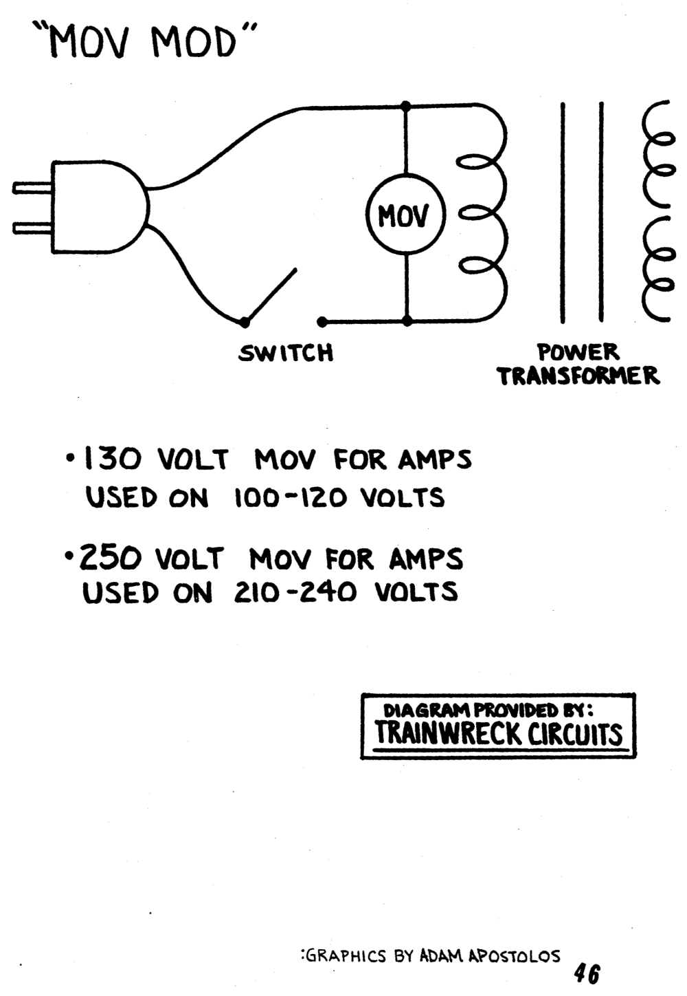
[Rob adds: The MOV Mod places an MOV (metal oxide varistor) across the power transformer's primary winding. The MOV will absorb high voltage power line spikes and prevent transformer and amp damage. With today's wall voltage exceeding 125 volts I recommend bumping the voltage rating of the MOV to 150 volts (270v international).]
Page 34
The Trainwreck Pages
OUTPUT SPIKE PROTECTION
This modification involves taking three 1N4007 silicon diodes in series with the banded end connecting to pin three of your output tubes and the other end to ground. You use one on each side of a push-pull output. So for example, on a 100 watt Marshall the two tubes on the left, either pin three of either one of those tubes can connect to this diode to ground. And on the other side either pin three can connect to the other set of diodes to ground, as the tubes on either side are in parallel.
We use 1N4007 silicon power diodes which are effective in suppressing spikes at certain frequencies. These will not necessarily prevent spiking on all amps! There is a fast recovery or high speed diode which will suppress higher frequency arcing however these diodes have a very distinct disadvantage as they alter the tone of the amp! They make the amp sound muddy as they bleed off high frequencies from the output transformer! Trainwreck does not use these kinds of diodes because of their effect on the tone.
While the Trainwreck method does not eliminate spiking in every amp, it does
not effect the tone at all. Every other method which will totally eliminate
spiking will have a negative effect on the tone of your amp.
Another point to remember concerning spiking is that hot biased amps tend to
generate more high voltage spiking than properly biased amps.
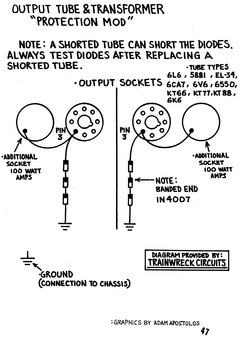
[Rob adds: The Protection Mod shunts voltage spikes from the output transformer primary winding to ground through three 10 cent 1N4007 diodes. Personally I prefer M.O.V.s connected from the power tube plates to the output transformer primary center tap to protect the output transformer.]
50 WATT MARSHALL BIAS MOD
Many early '70s Marshalls came from the factory with the bias connected to the cold side of the Standby switch. That is, a terminal on the Standby switch which does not have voltage until the switch is moved to the ON position. What this means to you is when you turn on the amp to warm-up, no bias voltage appears on the output tubes! When the amp is put into the ON position the bias voltage takes several seconds to build. In the meantime the tubes draw an extreme amount of current which can cause damage to the tubes or 'pop' the HT or high voltage fuse in your amp!
To determine if you have one of these amps you can turn the amp "ON", leave the Standby switch in the standby position and check pin 5 of a power tube for negative bias voltage which generally runs in the -30 volt range. If no bias voltage appears on pin 5 of the power tubes (also known as "output tubes"), you have an amp that requires this modification.
To accomplish this mod, first determine which terminals are the hot terminals on the Standby switch. Take a voltmeter, put it on an AC voltage range capable of measuring AC voltages over 300 volts. Connect one lead of the AC voltmeter to the chassis. Then probe terminals on the Standby switch with the other lead until you find one that reads AC voltage. Locate the wire coming off the terminal terminal on the Standby switch that runs to the bias diode and move it to one of the two terminals (it does not matter which one of these two) that has AC voltage on it.
WARNING! SHUT OFF THE AMP BEFORE SOLDERING THIS WIRE! ! AFTER YOU FIND THE PLACE THAT HAS THE VOLTAGE UNPLUG THE AMP!! ALSO MAKE SURE THE FILTER CAPS ARE DISCHARGED BEFORE YOU MOVE THE WIRE FROM THE 'COLD' TERMINAL AND SOLDER IT TO EITHER ONE OF THE "HOT" TERMINALS!
Page 35
The Trainwreck Pages
TROUBLE SHOOTING TIPS FOR MARSHALL OWNERS
Fuses on the Marshall: the "HT" fuse connects to the output transformer, the output tubes and some electrolytic capacitors. The vast majority of times when you blow an HT fuse in a Marshall is because of shorted output tubes. If your HT fuse blows and you replace it and it blows again, substitute output tubes. The second biggest cause of HT fuse blowing is a tube socket that has carbonized from high voltage arcing and has shorted out.
After eliminating these two possibilities then one would check for others, such as a bad filter cap which is probably the next most common cause. Then, of course, check the output transformer itself, the power diodes, etc.
When looking at a standard Marshall, either a four-input model or a factory MV with three preamp tubes, from the back (with the chassis in the normal upright position) the first tube on the left contains your gain stages. If you experience a lot of noise or microphonics in the amp, the tube on the FAR LEFT when viewing the amp from the back is the culprit.
The next tube (the middle one of the three) is a gain stage plus a cathode follower stage. The cathode follower stage is a circuit used to turn high impedance signals into low impedance signals to drive the tone circuitry. So the middle tube is also a gain stage and affects the tone controls. The third tube is the phase inverter which splits the signal into equal but opposite signals to drive the push-pull output stage.
For troubleshooting purposes one spare tube can be substituted one position at a time until the problem is eliminated. If the problem is not solved by this substitution technique take the amp to a service technician!
Make sure that the old style output selector is always CLEAN and TIGHT! Gaffer tape is NOT the recommended method of accomplishing this! A loose output selector or a bad speaker output cable can cause damage to output tubes and output transformers.
It is not recommended to use a Marshall with a conventional 'power soak', as the transformer was not designed to be used in this manner! POWER SOAKS CAN CAUSE DAMAGE TO THE OUTPUT TUBES AND THE OUTPUT TRANSFORMER! There does not seem to be any problems caused by the 'speaker emulators' on the market, such as the Groove Tube or Harry Kolbe "Silent Speaker" units but time will tell!
NEVER operate a tube amp without a suitable dummy load or speaker connected, or DAMAGE will occur!
Trainwreck does not recommend the use of a variac to boost the voltage going into a Marshall since it can drastically shorten the life of many components.
On certain early metal face Marshalls you may hear a "buzz" along with the normal Marshall "hiss", especially as you turn up the volume. Many of these amps have a ground loop problem. The ground from the diodes in the power supply section were connected to the front panel of the amp forming a ground loop which causes the "buzz". On those amps removing the ground from the front of the amplifier and reconnecting it to the back side of the chassis will eliminate this annoying buzz.
Page 36
The Trainwreck Pages
TROUBLE SHOOTING TIPS FOR MARSHALL OWNERS (CONT.)
Lead dress (HOW wires are routed) in Marshalls is critical for reducing noise. On old four-input Marshalls the filament leads, typically red and black, should be routed away from the tube socket and against the chassis.
The green grid leads, which are the leads that run to pins two and seven on the first two preamp tubes, should be raised in the air away from all the other leads. Also the leads on the controls, with the amp controls facing forward and the amp upside down, looking in, should be brushed toward the top of the chassis and towards the right side. There is a purple lead going to the Presence control, which comes from the feedback loop of the amp and that should be moved as much to the LEFT as possible.
On certain old Marshalls connect some of the grounds through the controls by soldering directly to the backs of the controls. The controls complete a mechanical ground connection to the chassis which can sometimes corrode. If you have a Marshall that has a "buzzy" or humming sound you can try jumping an alligator clip to the front of the chassis and connect it to the wire soldered across the backs of all the controls. If the hum or noise is eliminated, a wire may be soldered directly from that wire to the chassis, to ensure a positive connection.
On many old Marshalls the pilot light burns out and some collectors do not wish to alter the appearance by removing the original lens bezel. The bulb in question is a 6.3 volt incandescent job and a Trainwreck trick is to cut off the back of the pilot light (an EXACT O brand razor saw for plastics works great, says Steve) inside the amp CAREFULLY! Obtain a 6.3 volt "grain of wheat" bulb, solder it to the original leads, put it inside and reconnect the back . (Steve uses Jet Super Fast Dry crazy glue). The pilot assembly even looks stock from the outside and will continue to function as Marshall intended!
TUBE TIPS
Trainwreck often gets asked the difference between a 12AX7, a 7025 and an ECC-83. In days bygone, a 7025 was a premium version of a 12AX7. That is, a 12AX7 selected for its low noise.
An ECC-83 is just the Euro designation for a 12AX7.
In modern times, manufacturers label the same tubes 12AX7, ECC-83, or 7025 depending on the preference of the distributor! Though these 'types' are completely interchangeable, it should be noted that different brands of tubes can produce different tones, just as different brands of guitar strings or speakers have their characteristic tones. Anyone who is truly interested in experimenting may buy several different brands and types of these tubes and give them a trial. Also, you can mix and match; you can use a 12AX7 in one position, an ECC-83 in the next position and a 7025 in another position. You don't have to use the same brand in every position, nor do you have to use the same designation. Try different types and LISTEN; use the ones you like the sound of. It should also be noted that the 12AX7, 7025 and ECC-83 are all good substitutes for the 12AY7 found in some older Fender amps, including the 4x10" tweed Bassman. They are directly interchangeable. We would not recommend that if you run across some 12AY7s you try them in your Marshall; they are lower in gain and 'flatter' sounding than the 12AX7 types.
The 12AT7 used to drive the reverb tanks on Fenders and in the phase inverter of certain amps have the same pin configuration as 12AX7 types and in a pinch you may substitute a 12AX7 and a 12AT7. However the 12AT7 has a greater current handling capacity than a 12AX7 and 12AT7s should generally be used where specified!
Page 37
The Trainwreck Pages
FENDER TROUBLE SHOOTING GUIDE FOR TWO CHANNEL REVERB AMPS WITH SIX PREAMP TUBES
Looking at the back of the amp with the upper back panel removed, the first tube on the right (7025 or 12AX7) is the tube for the first or "Normal" channel. If this "Normal" channel is not working properly or making noises, this tube would be the one to suspect. The second 7025 is the tube (first preamp stage tube and tone driver tube – they do both functions) for the "Vibrato" channel. If you get microphonics or excessive noise in the second, or "Vibrato" channel, this would be the one to suspect. The third tube from the right is a 12AT7. It sits next to the right hand side of a small transformer (the reverb transformer) and acts as a reverb drive tube. This third tube supplies the signal to drive the reverb tank through the reverb drive transformer. If the reverb is not working but you can rock the amp with reverb control up and hear the springs 'crashing' I would suspect this 12AT7 first! If changing this 12AT7 does not cause the reverb to work then I would suspect an "open" driver or a break in a wire in the reverb tank. Also make sure that the reverb tank is plugged in the proper polarity as it will only work in one direction.
The fourth tube in the preamp (7025/12AX7) is the reverb recovery tube and a third gain mixer stage for the Vibrato channel. If the reverb is not functioning and rocking the amp does not cause a reverb 'crash' with the reverb control up, this 7025 is the one to suspect. If replacing this tube does not cause the reverb to function, an 'open' reverb tank is a likely culprit.
The fifth tube from the right (12AX7) is the tremolo oscillator tube. If your tremolo does not work, this is the tube to suspect. Note that in Fender amps the tremolo works by closing a circuit with the foot switch. If the foot switch is not plugged into the amp or not functioning properly to CLOSE the circuit, the tremolo will not work.
The sixth and final tube (12AT7) is the phase inverter tube. This 12AT7 provides the inverted signal and drives the output tubes. On the pre-CBS Fender circuitry a 12AX7 may be used in this position for a different tone with no harm. On the later models a 12AT7 should be used.
The next tubes over to the left are the power tubes. These are the tubes that do the amplifying and supply power to the speakers. It is very important in this position to have a fresh, preferably MATCHED set of tubes to get the maximum efficiency out of your amplifier.
If your amp has an odd number of output tubes, such as three, the one all the way over to the left is the RECTIFIER tube, typically a 5Y3GT, a 5AR4/GZ34 or 5U4GB. The function of this tube is to convert AC into DC. These tubes will either work or they won't! Occasionally one will have an intermittent short which will cause the fuse to blow.
MORE FENDER TROUBLE SHOOTING TIPS
On the pre-CBS Fender blackface series amplifiers, they used ½ watt carbon resistors in the preamp. With age, these tend to get very noisy. As the amp sits idling you will hear an assortment of snaps, crackles, pops and other noises. The first thing to try, to correct this, is a fresh set of preamp tubes. If the noise remains replace all 100K ohm resistors in the preamps with fresh ones of good quality. The 100K ohm resistors are the ones with the brown, black and yellow bands around them. There are eight of them altogether: three on each preamp and two in the reverb circuit (these last two resistors don't really make all that much noise).
Page 38
The Trainwreck Pages
CLEANING CONTROLS AND TUBE SOCKETS
WARNING! BEFORE ATTEMPTING ANY REPAIRS MAKE SURE THAT ALL CAPACITORS IN THE AMP ARE DISCHARGED! DO NOT ATTEMPT ANY REPAIRS IN THIS SECTION UNLESS THE AMP IS UNPLUGGED FROM THE AC LINE!
With age controls will become noisy. Tube sockets can become loose or corroded. Obtain a good, commercial quality control or contact cleaner spray from a reputable electronics supply house. Be sure to obtain a brand that states on the container that it is "safe for plastics". Some control cleaners contain a solvent that may actually dissolve parts inside your amp!
The way to clean controls is to squirt a SMALL amount of cleaner into the control and rapidly rotate the shaft back and forth along the entire length of travel.
Repeat this process for every control. This may also be used on open type switches, such as the mid-range and treble switches used on the Ampeg amps or the "Bright" switches used on Fender amps.
Tube socket contacts can spread over time, not making proper contact with the pins of the tubes. Using a strong pin or other object, slightly bend the contacts inward closing the gap slightly on the contacts in the sockets. You can also clean socket contacts with the same control cleaner spray described above. This will do much to reduce amplifier noise and increase reliability.
NOTE: DO NOT SOAK THE SOCKETS WITH CONTACT CLEANER! USE NO MORE THAN IS NEEDED ΤΟ DO ΤΗΕ JOΒ!
If you notice that the tube sockets do not respond to re-tensioning (have little 'spring' to them) it is time to replace that whole socket. Also note any charring or carbon build-up on the socket – these sockets too must be replaced. Sockets that are exceptionally dirty, with pitting of the metal surfaces, are also best replaced.
It should be noted that certain controls on certain amps will make noises no matter how much you clean them, such as the PRESENCE control on many Marshall amps (also on Trainwreck amps), as these contain DC voltages. If a typical control cannot be made silent using cleaner it is probably worn out and should be replaced. The exception to this rule is if you are a collector of vintage amps and you want to retain your amps originality, as long as the control functions and the noise that results does not drive you crazy, I would leave it alone.
The same control cleaner described above can be used to clean the controls and switches in your guitar. However I recommend HUGE amounts of paper towels behind and around the controls and switches so that you do not get control cleaner on the finish of your guitar, or saturate the wood!
RECTIFIER TUBES
The common rectifier tubes used in guitar amps are the 5Y3, 5AR4/GZ34 or 5U4. These tubes are directly interchangeable in most guitar amps. However each tube produces a slightly different tonal characteristic in the amp. The 5AR4 produces a tone closest to solid state silicon rectifiers that are most common in amps today. This is because this rectifier has less of the characteristics known as voltage drop and sag; that is, as the amplifier draws current the voltage across the tube drops (sag is the voltage drop across the tube that increases with current draw).
Page 39
The Trainwreck Pages
RECTIFIER TUBES (CONT.)
The 5AR4/GZ34 has the least loss of voltage with current draw. The 5U4 tube has slightly more voltage sag with current draw than a 5AR4/GZ34. The 5Y3 has the most voltage sag and therefore has the 'softest' tone. Also if you have an amp that "eats" output tubes it will be easiest on the amp to use a 5Y3. One can substitute these tubes and judge for one's self which one provides the basic tone that one likes but keep in mind the 5U4 requires an extra amp of 5V heater current.
Many companies make a solid state replacement for these rectifier tubes. These solid state units tend to 'tighten up' the tone and make it more dynamic. However they also tend to remove the 'singing' quality in certain amps! If you are going to substitute make sure that the voltages will not exceed the voltage ratings of your output tubes and power filters! For example, a Fender blackface Deluxe with a solid state rectifier in place will exceed the voltage ratings of both the tubes and the power filters and is most emphatically NOT recommended! However the same mod will work just fine on a Super Reverb!
TIPS FOR HIWATT OWNERS
The vintage DR series amps were bullet proof! They had only one MAJOR design flaw from the factory. That was the decision to use one watt carbon screen resistors. While I'm sure Hiwatt thought that their amps were phenomenally loud and no one would ever want to turn one up to the point of distortion, actually many people do! When a Hiwatt equipped with EL-34s reaches distortion, especially when outfitted with modern EL-34s, the screen current draw exceeds the ratings of these one watt resistors and they do burn up. When these resistors burn, they open up, shutting off that tube and eventually shutting down the amp. Trainwreck recommends that anyone with a Hiwatt replace all one watt screen resistors with five watt wire wound resistors.
Another Hiwatt mod which may be useful concerns wiring layout. Although the Hiwatt layout and wiring is among the neatest of any guitar amp ever built they do have a problem with buzz and noise caused by ground loops. In order to obtain a neat appearance inside the amp one ground point was connected to another by ground wires which are hidden underneath the preamp circuit board. This can result in an amp, which when turned to "10", is buzzy and noisy. Locating all the grounds in a Hiwatt, disconnecting the subterranean wire and running each ground individually to the front of the chassis will make the Hiwatt much quieter and also tends to improve the tone! This is a tricky operation as these ground wires are hidden and should be done by a tech with some experience with this brand.
The Trainwreck Pages by Ken Fischer
Page 40
[PDF to OCR to HTML, DOC, ODT & searchable PDF by Rob Robinette]
[This webpage is available in .pdf form: The Trainwreck Pages by Ken Fischer with additional info by Rob Robinette.pdf]
[ How Amps Work ] [ Overdrive ] [ 5E3 Mods ] [ 5F6A Mods ] [ AB763 Mods ] [ DRRI & 68 CDR Mods ] [ How the 5E3 Deluxe Works ] [ How the AB763 Works ] [ AB763 Models ] [ Tube Bias Calculator ] [ Amp Troubleshooting ] [ Deluxe Models ] [ Deluxe Micro Amp ] [ Bassman Micro Amp ] [ Champ Micro Amp ] [ My 5E3 Build ] [ Reverb & Tremolo ] [ SixShooter ] [ Spice Analysis ] [ VHT Special 6 Ultra Mods ] [ Telecaster Mods ] [ Android Tube Bias Calculator App ] [ The Trainwreck Pages ] [ Fender Input Jacks ] [ B9A Prototype Board ]