[ How Amps Work ] [ Overdrive ] [ 5E3 Mods ] [ 5F6A Mods ] [ AB763 Mods ]
How Fender Normal/Bright/Hi/Low Input Jacks Work
And what jumpering the channels does
By Rob Robinette
Many guitar amplifiers use Fender's very clever Bright/Normal/Hi/Lo input scheme to offer four input jacks each with a distinctive tone. Adding a jumper cable between the Bright and Normal channels will parallel the signal to both channels' preamp tubes and offers even more input tone options.
Note that the jumpering discussion on this page does not apply to brown and blackface Fender amps with reverb because the reverb or vibrato channel has an extra gain stage that puts it out of phase with the normal channel. Jumpering the two channels together won't hurt anything but you'll have thin tone and odd control interaction. A few non-reverb brown and blackface amps also have out of phase channels too. If you add a jumper and it sounds like crap your channels are probably out of phase.
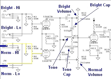
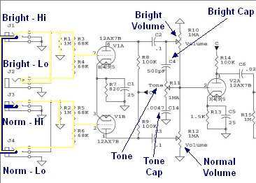
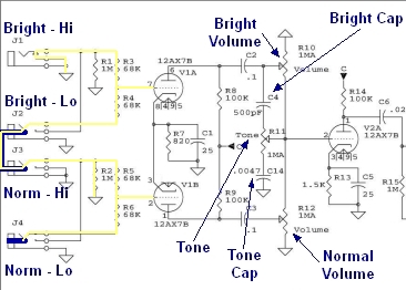
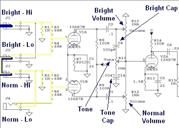
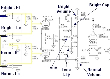
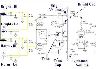
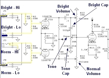
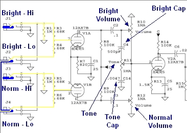
Input Schematic
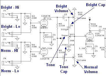
Typical Normal/Bright Hi/Lo Input Jacks
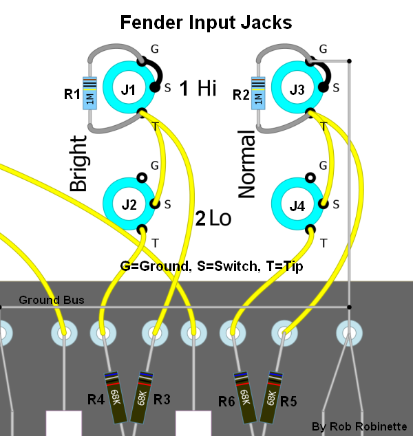
Component numbers on this layout diagram match the schematics on this page. Resistors R1 and R2 (soldered directly to the Hi input jacks) are input resistors and set the amp's input impedance but also function as the first preamp tube's grid leak resistors. Resistors R3, R4, R5 and R6 are grid stopper resistors (remove frequencies above human hearing) but also function as mixing resistors to reduce interaction between two simultaneous inputs. The input jacks' Switch and Tip are connected when no plug is inserted. The connection between Switch (also called Shunt) and Tip is broken when a plug is inserted. The upper jacks' Switch terminals are jumpered to ground to silence the channel when no input plug is inserted.
The schematics on this page are from the Weber 5e3 Tweed Deluxe amplifier.
Bright Hi and Lo are the Bright/Instrument channel because of capacitor C4, the 'Bright Cap,' (see graphic below) which boosts high frequencies by bypassing them around the Bright Volume control. The Bright Cap only functions at lower volume levels so it's usually preferred for lower volume playing. If you find the Normal channel too dark at low volume try the Bright channel. Note that the only difference between the Normal and Bright channels is the Bright Cap and at max volume there is no difference between the Bright and Normal channels.
The Hi and Lo inputs differ in signal intensity, input impedance and grid stopper resistance. The Lo inputs form a voltage divider using the two 68k grid stopper resistors. This voltage divider cuts the source signal in half (-6dB)--yes, half of the guitar signal is bled to ground. The Lo inputs are attenuated by slightly more than -6dB to offer less gain and more clean headroom. If you find you prefer the Lo inputs I recommend you try using the Hi inputs and turn down the guitar's volume control. You get pretty much the same outcome but you have control at the guitar but the Low jack's low input impedance can remove some high frequencies from the guitar pickup so the guitar tone is typically a little less bright when compared to the Hi jack.
With 5E3 Deluxe style amps the Bright Volume, Normal Volume and Tone controls all interact with one another even when only one input jack is in use. This is especially true near minimum and maximum tone and volume settings. With a guitar plugged into the Normal channel the Bright Volume control interacts with the Bright Cap to form a variable RC (resistance capacitance) low pass filter. At minimum bright volume and maximum bright tone the Bright Cap shunts Normal channel high frequency directly to ground. This is why the brightest tone comes at around 8 or 9 (out of 12 because the 5E3 tone and volume knobs are labeled from 1 to 12) on the tone control.
Normal - Hi Input
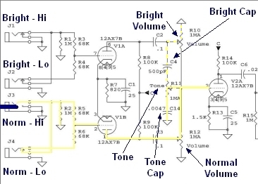
Note the labeled primary tone shaping components in the schematic: Normal Volume pot, Tone pot, Tone Cap, Bright Volume pot and Bright Cap.
Guitar plugged into Normal/Microphone - Hi jack.
Resistor R2 is acting as the input impedance resistor. Resistors R5 and R6 in parallel are acting as the grid stopper resistors.
Signal flow shown in yellow. Input resistance is R2: 1 megaohm.
With the Normal - Low jack switch terminal closed the signal has a parallel path to V1B's grid so the grid stop resistance is R5 and R6 in parallel: 1/(1/68k +1/68k) = 34 kilohms.
Notice how the signal travels from the V1B* preamp tube through both volume pots, the tone pot, bright cap and tone cap. When the Tone control is turned up for a bright tone and the Bright Volume is turned down capacitor C4 (Bright Cap) works as a low pass filter and bleeds high frequencies through the Bright Volume's ground. This is one reason why the volume and tone controls are so interactive.
*Note: The Weber 5E3 schematic used on this page have V1A and V1B reversed from the 5E3 norm. V1A is actually used for the Normal channel and V1B is used for the Bright channel.
Normal - Low -6dB Input
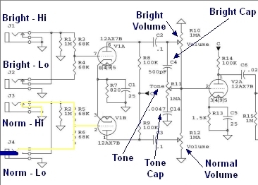
Guitar plugged into Normal - Lo jack.
Resistors R5 & R6 are acting as the input impedance resistors. Resistor R6 is acting as the grid stopper resistor. R5 and R6 form a voltage divider and effectively cut the input signal from the guitar in half.
Input resistance is R5 + R6: 136k. Grid stop resistance is R6: 68k. Lower input resistance (lower input impedance), higher grid stop resistance and the voltage divider all attenuate the signal for slightly more than -6dB compared to the Hi jack.
The Low jack's low input impedance can suppress some high frequencies from the guitar pickup so the guitar tone is typically a little less bright than when compared to the Hi jack.
Bright - Hi Input
The 'Bright Cap' C4 bypasses high frequencies around the Bright Volume control to boost the Bright Channel's highs when playing at lower volume. The Bright Cap is the only difference between the Normal and Bright channels. This is the input I use most on my 5E3 Deluxe guitar input because it doesn't get too dark at low volume and near max volume it has the same tone as the Normal channel.
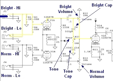
Guitar plugged into Bright - Hi jack.
Resistor R1 is acting as the input impedance resistor. Resistors R3 and R4 in parallel are acting as the grid stopper resistors.
Input resistance is R1: 1M. Grid stop resistance is R3 and R4 in parallel: 1/(1/68k +1/68k) = 34k. These values are identical to the Normal - Hi input--the only difference between the Normal and Bright channels is the Bright channel's Bright Cap.
Bright - Lo -6dB Input
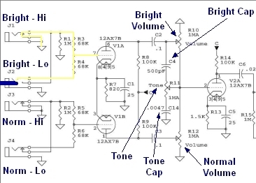
Guitar plugged into Bright - Lo jack.
Resistors R3 & R4 are acting as the input impedance resistors. Resistor R4 is acting as the grid stopper resistor. R3 and R4 form a voltage divider and effectively cut the input signal from the guitar in half.
Input resistance is R3 + R4: 136k. Grid stop resistance is R4: 68k. Lower input resistance (lower input impedance), higher grid stop resistance and the voltage divider all attenuate the signal for slightly more than -6dB. These values are identical to the Normal - Lo input.
Two Instruments In One Channel
Guitar #1 plugged into Normal - Hi jack.
Input resistance is R2: 1M. Grid stop resistance is R5: 68k.
Guitar #2 plugged into Normal - Lo jack.
Input resistance is R5 + R6 + R2: 68k + 1M = 1.136M. Grid stop resistance is R6: 68k.
With two guitars connected resistors R5 and R6 also function as mixing resistors to reduce interaction between the two inputs. Note how the two 68k grid stopper resistors do not form a voltage divider so both inputs act like Hi inputs. The two inputs are almost identical and for practical purposes are balanced.
Four Simultaneous Instruments
Guitar plugged into Normal - Hi jack. Input resistance is R2: 1M. Grid stop resistance is R5: 68k.
Guitar plugged into Normal - Lo jack. Input resistance is R5 + R6 + R2: 68k + 68k + 1M = 1.136M. Grid stop resistance is R6: 68k.
Guitar plugged into Bright - Hi jack. Input resistance is R1: 1M. Grid stop resistance is R3: 68k.
Guitar plugged into Bright - Lo jack. Input resistance is R3 + R4 + R1: 68k + 68k + 1M = 1.136M. Grid stop resistance is R4: 68k.
With four guitars connected resistors R3, R4, R5 and R6 also function as mixing resistors to reduce interaction between the inputs. Note how none of the 68k grid stopper resistors form a voltage divider so all four inputs act like Hi inputs. The four inputs are almost identical and for practical purposes are balanced.
Empty Input Jacks
With no input connections all four input jack tips are grounded through the jacks' switch terminals. This grounds tube V1A's and V1B's control grids to reduce noise. Grounding the input jack tips also is a safety feature. If high voltage were to make it to the grid circuit it would short to ground and blow a fuse rather than sit there waiting for you to plug your guitar into it.
Using a Jumper Between the Normal and Bright Channels
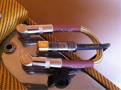
Bright - Hi input used with 6" patch cable between Bright - Lo and Normal - Hi. Photo by sookwinder.
A jumper can be plugged between the Normal and Bright Channels to achieve a tone somewhere between Normal and Bright. The parallel amplification through triode V1A and V1B also adds "fullness" and "complexity" to the amp's tone.
Note that with all patch setups the channel the guitar is plugged into will be the dominant channel. By selecting the correct patch you can control the amount of dominance.
Even when using a patch cable the guitar will 'see' only one combined input impedance.
Normal - Hi With Jumper From Normal Lo to Bright Hi
This is probably the most commonly used jumper configuration and will give you the 'fattest' parallel tone: The guitar plugged into the Normal - Hi jack and a jumper between the Normal - Lo and Bright Hi jacks.
The guitar 'sees' only one input resistance at the Normal - Hi jack which is R2 parallel (R5 + R6 + R1) = 1/ (1/1M + (1/(68k + 68k + 1M)) = 532k.
The Normal - Hi grid stop resistance is R5: 68k.
The jumpered Bright - Hi grid stop resistance is R6 + (R3 parallel R4): 68k + 1/(1/68k + 1/68k) = 102k.
So the input resistances are identical between the channels but the jumpered Bright input has 50% more grid stop resistance. This patch slightly favors the Normal channel tone. Note neither channel is attenuated with a voltage divider so all three inputs act like Hi inputs and the tone will be nice and 'fat.'
Normal - Lo With Jumper From Normal Hi to Bright Lo
Guitar plugged into the Normal - Lo jack and a jumper between the Normal - Hi and Bright Lo jacks.
Input resistance at the Normal - Lo jack is R5 + R6 + (R2 parallel R3 + R4) = 136kk + 1/(1/1M + 1/136k) = 256k.
The Normal - Lo grid stop resistance is R6: 68k.
The jumpered Bright - Lo grid stop resistance is R5 + R4: 68k + 68k = 136k. R3 and R4 form a voltage divider and cut the Bright signal by 50%.
Since the Bright channel has 100% more grid stop resistance and the voltage divider formed by R3 and R4 cuts the Bright signal by 50% (-6dB) this patch favors the Normal channel and will not sound as 'fat' because of the -6dB attenuation of the Bright channel.
Bright - Hi With Jumper From Bright Lo to Normal Hi
This is probably the second most commonly used jumper configuration and will give you the same 'fat' parallel tone as the Normal - Hi With Jumper from Normal Lo to Bright Hi but with the benefit of the Bright Cap. Guitar plugged into the Bright - Hi jack and a jumper between Bright - Lo and Normal - Hi jacks.
Input resistance is R1 parallel (R3 + R4 + R2) = 1/(1/1M + 1/(68k + 68k + 1M)) = 532k.
Bright - Hi grid stop resistance is R3: 68k.
The jumpered Normal - Hi grid stop resistance is R4 + (R5 parallel R6): 68k + 1/(1/68k + 1/68k) = 102k.
This patch slightly favors the Bright channel tone. Note neither channel is attenuated with a voltage divider so all three inputs act like Hi inputs and the tone will be nice and 'fat.'
Bright - Hi With Jumper From Bright Lo to Normal Lo
Guitar plugged into the Bright - Hi jack and a jumper between Bright - Lo and Normal - Lo jacks.
Input resistance is R1 in parallel with (R3 + R4 + R5 + R6) = 1/ (1/1M + 1/(68k +68k + 68k + 68k)) = 214k.
Bright - Hi grid stop resistance is R3: 68k.
The jumpered Normal - Lo grid stop resistance is R4 + R6 + R5: 68k + 68k + 68k = 204k. R5 and R6 form a voltage divider and cut the Normal channel signal by 50%.
Since the Bright channel has 200% more grid stop resistance and the Normal channel signal is cut by 50% (-6dB) by the voltage divider formed by R5 and R6 this patch favors the Bright channel and will not sound as 'fat.'
Bright - Lo With Jumper From Bright Hi to Normal Hi
Guitar plugged into the Bright - Lo jack and a jumper between Bright - Hi and Normal - Hi jacks.
Input resistance is R4 + R3 + (R1 parallel R2) = 68k + 68k + 1/(1/1M + 1/1M) = 636k.
Bright - Lo grid stop resistance is R4: 68k.
The jumpered Normal - Hi grid stop resistance is R3 + (R5 in parallel with R6): 68k + 1/(1/68k + 1/68k) = 102k.
This patch slightly favors the Bright channel tone. Note neither channel is attenuated with a voltage divider so all three inputs act like Hi inputs and the tone will be nice and 'fat.'
Bright - Lo With Jumper From Bright Hi to Normal Lo
Guitar plugged into the Bright - Lo jack and a jumper between Bright - Hi and Normal - Lo jacks.
Input resistance is R4 + R3 + (R1 parallel R6 + R5) = 68k + 68k + 1/(1/1M + 1/(68k + 68k)) = 256k.
Bright - Lo grid stop resistance is R4: 68k.
The jumpered Normal - Lo grid stop resistance is R3 + R6 + R5: 68k + 68k +68k = 204k. The Normal channel's signal is cut in half (-6dB) by the voltage divider formed by R5 and R6.
This patch heavily favors the Bright channel and the signal will not sound as 'fat.'
Two Instruments With A Jumper
Two Guitars plugged into the Bright and Normal - Hi jacks and a jumper between the Lo jacks.
Input resistance is the same for both guitars: (R1 parallel (R3 + R4 + R6 + R5 + R2)) = 1/ (1/1M + 1/(68k + 68k +68k +68k +1M)) = 560k.
Bright - Hi Guitar grid stop resistance is R3 68k.
Normal - Hi Guitar grid stop resistance is R5 68k.
With two instruments and a jumper (any position) the grid stop resistance will always be 68k and the input resistance will always be between 532k and 560k. None of the 68k grid stop resistors form a voltage divider so neither channel is subject to -6dB attenuation. All the inputs act like Hi inputs so the channels are balanced.
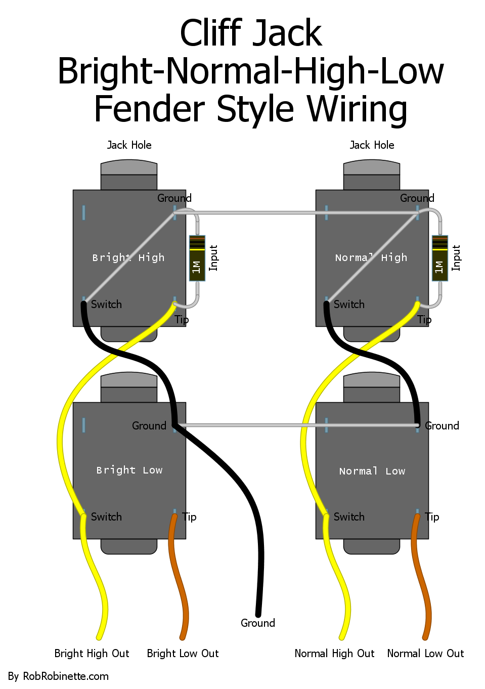
Common Input Jack Wiring
This is how many people actually wire the four input jacks. The jacks are oriented so the upper jacks' Tip terminals and lower jacks' Switch (shunt) terminals are touching and they are soldered together. Doing this deletes the jumper between the two jacks.
Also, the 1M Input resistors' legs are used to form the jumper from the upper jacks' Ground to Switch terminals. Insert the resistor leg through the hole in the Ground terminal and through the Switch terminal hole, then bend the resistor around to make contact with the Tip terminal and solder in place.
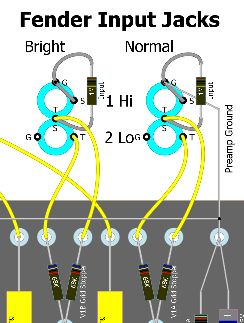
The Tip and Switch terminals are soldered together.
Use 2 Input Jacks Instead of 4
This is how to drop the two "Low" jacks from any amp with the standard Bright/Normal/High/Low four input circuit. Both jacks are Hi inputs.
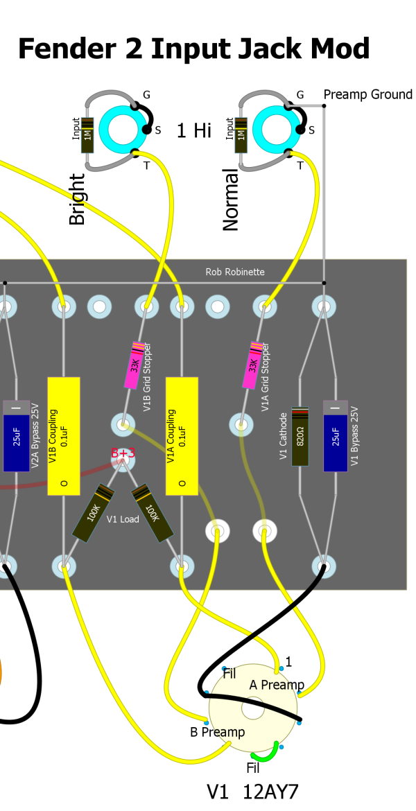
Note the grid stopper resistors (pink) were reduced from 64k to 33k because the Hi input jacks use both 64k grid stoppers in parallel for 32k of grid stop resistance.
Another option is instead of removing one 64k grid stopper resistor and changing out the other for a 33k as shown above, you can simply run a jumper between the two 64k resistors so the signal goes through both resistors for 32k of grid stop resistance.
Channel Jumper Switch
Since channel jumpering is so common among Fender players this mod will let you leave your jumper cable at home and jumper the Bright and Normal channels with the pull of the Normal volume knob. You can plug your guitar into any jack and you will get a Hi jack-to-Hi jack jumper.
Just swap out the Normal Channel volume pot for a 1MA Push-Pull pot with DPDT switch (Bourns Model PDB183-GTR). If you prefer you can use a separate ON-ON DPDT switch to do the same thing. This switch will work on any amp that has Fender style four inputs (Bright/Normal/Hi/Lo).
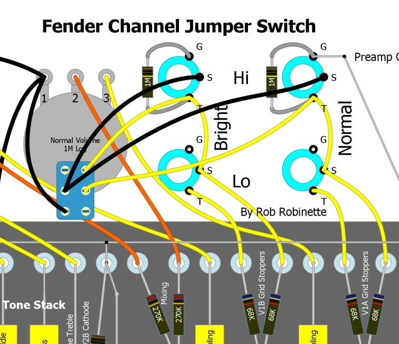
Note the wires between the Hi Jacks' switch and ground terminals have been cut.
With the Normal volume knob down the input jacks function normally with the jacks grounded when nothing is plugged in. Pull the Normal volume knob up and the two Hi jacks are jumpered together for a fatter tone. Your guitar signal will flow through both V1A and V1B preamp tubes in parallel which adds some texture and complexity to the tone.
To install the switch first remove or cut both Hi jacks' wire that runs between their ground and switch terminals. Then replace the Normal volume pot and wire the three volume pot terminals normally. Wire the DPDT switch part of the pot as in the layout above and you're done.
The Switchcraft 12A Switched 1/4" Input Jack
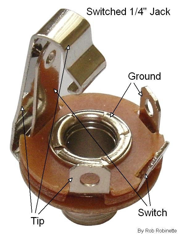
The Tip and Switch (also called the Shunt) terminals are in contact when no plug is inserted. Inserting a plug breaks the contact. Fender "Hi channel" input jacks have a jumper between the Ground terminal and the Switch so with no plug inserted all three terminals are grounded.
Hi/Low Input Switch
This switch allows you to use one input jack and select Hi or Low output. The switch inserts a 33k/33k voltage divider which dumps half the guitar audio signal to ground--just like a standard Fender Low Input jack. With the switch open you have the High Input and switch closed you get the Low.
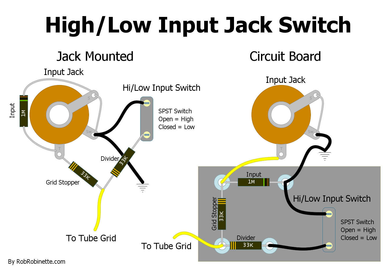
Jack mounted circuit on the left, circuit board version on the right. Download the high resolution pdf here and DIYLC file here.
In the High position input impedance is 1M and grid stopper resistance is 33k--exactly as the 5E3 Deluxe.
In the Low position input impedance is 62k (1M in parallel with 66k) and grid stopper resistance is 33k.
The factory 5E3 has a Low input impedance 138k and grid stopper resistance of 68k but this mod will give us a tone that's so close to factory that I'll buy you a case of beer if you can hear a difference.
By Rob Robinette
References
RCA Corporation, RCA Receiving Tube Manual, RC30.
Merlin Blencowe, Designing Tube Preamps for Guitar and Bass, 2nd Edition. This is my personal favorite tube amp book.
Merlin Blencowe, Designing High-Fidelity Tube Preamps
Morgan Jones, Valve Amplifiers, 4th Edition.
Richard Kuehnel, Circuit Analysis of a Legendary Tube Amplifier: The Fender Bassman 5F6-A, 3rd Edition.
Richard Kuehnel, Vacuum Tube Circuit Design: Guitar Amplifier Preamps, 2nd Edition.
Richard Kuehnel, Vacuum Tube Circuit Design: Guitar Amplifier Power Amps
Robert C. Megantz, Design and Construction of Tube Guitar Amplifiers
Neumann & Irving, Guitar Amplifier Overdrive, A Visual Tour It's fairly technical but it's the only book written specifically about guitar amplifier overdrive. It includes many graphs to help make the material easier to understand.
T.E. Rutt, Vacuum Tube Triode Nonlinearity as Part of The Electric Guitar Sound
[ How Amps Work ] [ Overdrive ] [ 5E3 Mods ] [ 5F6A Mods ] [ AB763 Mods ] [ DRRI & 68 CDR Mods ] [ How the 5E3 Deluxe Works ] [ How the AB763 Works ] [AB763 Models] [ Tube Bias Calculator ] [ Amp Troubleshooting ] [ Deluxe Models ] [ Deluxe Micro Amp ] [ Bassman Micro Amp ] [ Champ Micro Amp ] [ My 5E3 Build ] [ Reverb & Tremolo ] [ SixShooter ] [ Spice Analysis ] [ VHT Special 6 Ultra Mods ] [ Telecaster Mods ] [ Android Tube Bias Calculator App ] [ The Trainwreck Pages ] [ Fender Input Jacks ] [ B9A Prototype Board ]