
Tube Amp Spice Analysis
By Rob Robinette
LTSpice is a very powerful and reasonably easy to use free circuit simulation program. You can download the blackface Bassman, Deluxe Reverb and 5E3 Deluxe by Carl Gigun LTSpice models (I did not create these models). The following are some simulations I drew up and ran to better understand the circuits.
Fixed Bias Analysis
I modeled the 5F6A tweed Bassman's fixed bias circuit to see how changing voltages and component values affected its voltage output, capacitor charging time and ripple removal. I really learned a lot about how the circuit works by looking at the AC, DC and ripple waveform plots as they move through the circuit. Just load an .asc file and click the "Run" command.
5F6A Non-Adjustable Fixed Bias
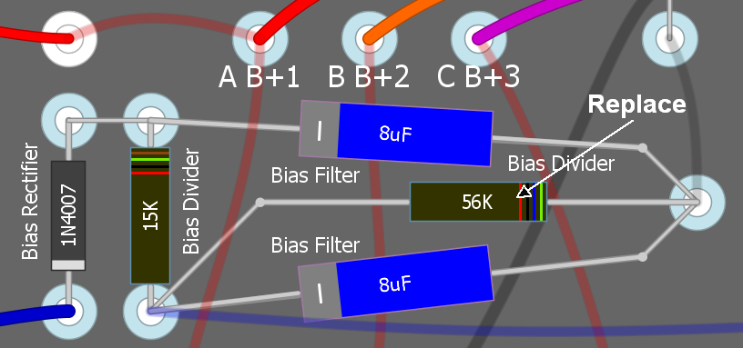
Approximately 45 volts AC RMS enters the circuit from the power transformer via the blue wire at bottom left. Bias voltage flows out the blue wire connected to the bottom of the 15k resistor. The three-way junction at far right is connected to ground. With 45V AC input this circuit puts out a DC bias voltage output of -49v.
5F6A Fixed Bias LTSpice Model
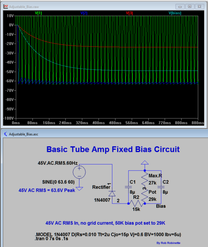
The bias circuit modeled in LTSpice. The green plot is 45v AC RMS (63.6v peak) 60Hz voltage at node 1 (rectifier diode input). The dark blue line is the DC voltage at node 2 (first filter cap C1). Note how it jumps up and down--that's ripple voltage. The light blue line is DC bias voltage (second filter cap C2). Note there is absolutely no ripple visible. The red line is the DC voltage at node 3 (between bias pot and 27k resistor). The bias pot is set at 29k + the 27k resistor equals the 5F6A standard 56k of bias resistance. The bias voltage stabilized at -49v in about half of a second (500ms). If a 50K Linear bias pot is used along with a 27k bias resistor the bias voltage can be set from -40V (hottest bias) to -52 (coolest bias) with 45V AC input voltage. Download the 5F6A bias circuit LTSpice file here.
45 volts of AC is the standard voltage for power transformer bias taps. To simulate 45v RMS AC I used a 63.6 peak voltage sine wave at 60Hz. With the bias pot set to 29k + the 27k bias resistor = 56k of resistance just like the stock 5F6A non-adjustable bias circuit.
Universal HT Tap Fixed Bias
Here I model my "universal HT (high voltage) tap fixed bias circuit." I wanted to see the affect of placing the 220k voltage dropping resistor before and after the rectifier diode.
Universal HT Tap Fixed Bias Circuit With 220k Resistor First
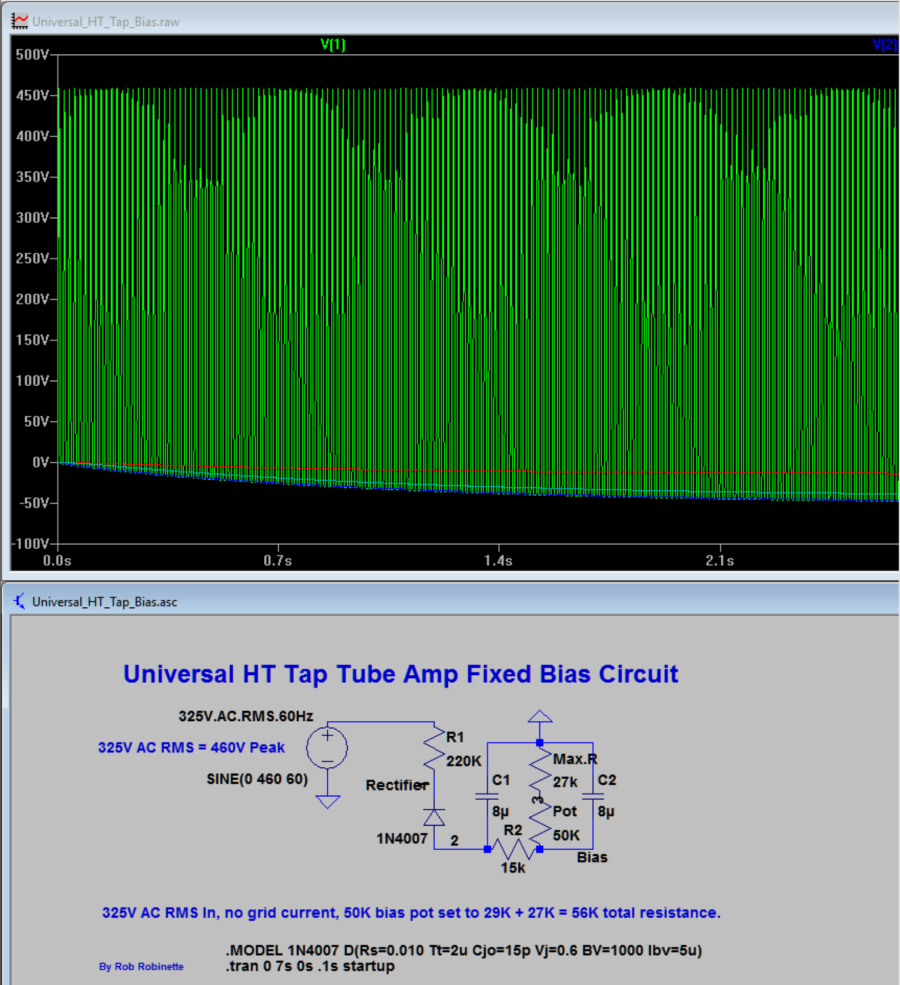
460 peak volts AC is applied to resistor R1. 455p volts flows out of the resistor into the rectifier. The 455 peak volts AC is plotted in green. The dark blue line shows the DC voltage at the first filter cap C1. The light blue line is the DC voltage at the second filter cap C2 (bias voltage). The red line is the DC voltage between the bias pot and 27k resistor. The bias pot is set to 50k (max hot bias). Download the LTSpice Universal HT Tap Bias circuit file here.
I ran the Universal HT (high voltage) Tap Bias Circuit with the 220k resistor first and again with the diode first. There is no bias voltage difference between the two configurations but putting the resistor first helps protect the diode from voltage spikes. The first filter cap voltage is shown in dark blue plot. The green plot is the voltage between the diode and 220k resistor, dark blue is first filter cap, light blue is second filter cap (bias voltage tap) and the red is between the pot and 27k resistor.
Universal HT Tap Fixed Bias Circuit With Rectifier Diode First
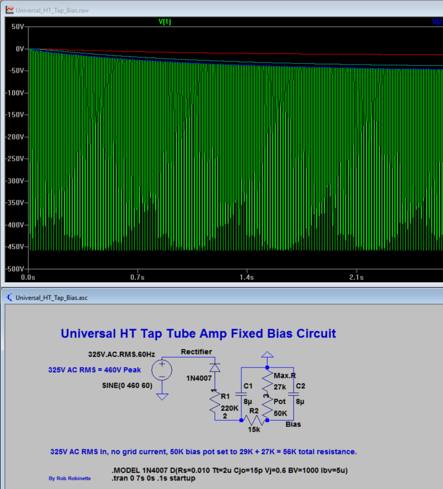
Since the rectifier diode comes first node 1 (between diode and 220k resistor) sees only 458 peak volts of pulsing negative DC. The dark blue line shows node 2 DC voltage (first filter cap C1). The light blue line is bias voltage (second filter cap C2) and the red line is the junction of the bias pot and 27k resistor.
I modeled the circuit using 8uF (5F6A original value), 25uF, 50uF and 100uF filter caps. Due to the high impedance nature (high voltage, low current) of the HT source voltage the circuit gets very slow to come up to bias voltage at startup with a pair of 50uF and especially 100uF bias filter caps. I've read the main concern with this slow bias cap charging time is with a power interruption that would drop the bias voltage (reduce toward 0v) and expose the power tubes to very hot bias but it seems to me the main filter caps would drain much faster than the bias caps due to the bias circuit's very low current draw.
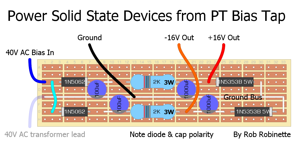
Power for Solid State Devices from PT Bias Tap Analysis
This power supply circuit can supply solid state devices with +16v and -16v from the power transformer 40 volt bias tap.
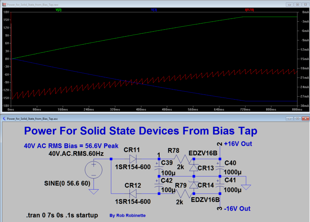
Green trace shows + output voltage of 16.25v at node 2 (upper right of schematic). Blue trace shows - output voltage of -16.25v at node 3. Red trace shows current through resistor R78 of 19ma and .72 watts of dissipation. Download the power supply LTSpice file here.
References
RCA Corporation, RCA Receiving Tube Manual, RC30.
Merlin Blencowe, Designing Tube Preamps for Guitar and Bass, 2nd Edition.
Merlin Blencowe, Designing High-Fidelity Tube Preamps
Morgan Jones, Valve Amplifiers, 4th Edition.
Richard Kuehnel, Circuit Analysis of a Legendary Tube Amplifier: The Fender Bassman 5F6-A, 3rd Edition.
Richard Kuehnel, Vacuum Tube Circuit Design: Guitar Amplifier Preamps, 2nd Edition.
Richard Kuehnel, Vacuum Tube Circuit Design: Guitar Amplifier Power Amps
Robert C. Megantz, Design and Construction of Tube Guitar Amplifiers
Neumann & Irving, Guitar Amplifier Overdrive, A Visual Tour It's fairly technical but it's the only book written specifically about guitar amplifier overdrive. It includes many graphs to help make the material easier to understand.
T.E. Rutt, Vacuum Tube Triode Nonlinearity as Part of The Electric Guitar Sound
[ How the 5E3 Deluxe Works ] [ Deluxe Models ] [ DRRI & 68 CDR Mods ] [ Amp Troubleshooting ] [ My 5E3 Build ] [ Spice Analysis ] [ The Trainwreck Pages ] [ Fender Input Jacks ] [ B9A Prototype Boards ]