5E3P Proluxe Guitar Amp Build
This Proluxe amp kit was my first amp build. I took the plunge a few years ago and ordered a BootHillAmps.com 35watt 5E3P Proluxe amplifier kit. This amp uses the Fender 5E3 tweed Deluxe preamp and the Fender 5E5-A Pro power amp to create a very powerful but still tweedy amp. The resulting Proluxe is a classic all tube (including tube rectifier) guitar amp using two preamp tubes and a pair of 6L6 push-pull fixed bias power tubes. The output transformer, filter caps and rectifier tube are all upgraded to handle the higher 6L6 fixed bias output.
If you are considering building a Deluxe or Proluxe take a look at the 5F11 tweed Vibrolux. It's not any more difficult to build but it includes tremolo and fixed bias. I'm a big fan of tremolo. Also the following generation 6G3 brownface Deluxe is a very cool amp. It has tremolo too but adds a better sounding long tail pair phase inverter. If I built one of these amps I'd add a switched bias mod so I could get a tweed style cathode biased tone out of it. Mojotone sells very nice 5F11 Vibroluxe and 6G3 Deluxe kits.
The Proluxe option adds flexibility because you can swap in a lower voltage 5Y3 rectifier tube and you can run lower power 6V6 power tubes like the standard 5E3 Tweed Deluxe. Here's my 5E3 modifications page.
I highly recommend a kit build if you are interested in the electronic theory of tube amplification. I went from being a lousy solderer and having a casual knowledge of electronics (I couldn't calculate the value of 3 parallel resistors) and having no idea how tubes worked to really understanding electronic amplification and tube theory and my soldering skills are now top notch. Researching my kit build motivated my learning and I have really enjoyed the entire process--and then of course there's the end result--having a nice self-built tube guitar amplifier to play through.
The kit comes with a very nice chrome chassis, circuit board and all the components needed to build a combo amp except tubes, transformers, speaker and cabinet which are available from BootHillAmps.com if you want to source the entire amp at one time. The chassis works perfectly as an amp head or combo amp. Want to know more about how amplifiers work? See my How Guitar Tube Amplifiers Work webpage.
WARNING: A tube amplifier chassis contains lethal high voltage even when unplugged--sometimes over 700 volts AC and 500 volts DC. If you have not been trained to work with high voltage then have an amp technician service your amp. Never touch the amplifier chassis with one hand while probing with the other hand because a lethal shock can run between your arms through your heart. Use just one hand when working on a powered amp. See more tube amplifier safety info here.
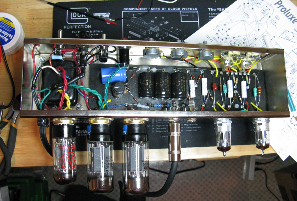
The completed and functional chassis
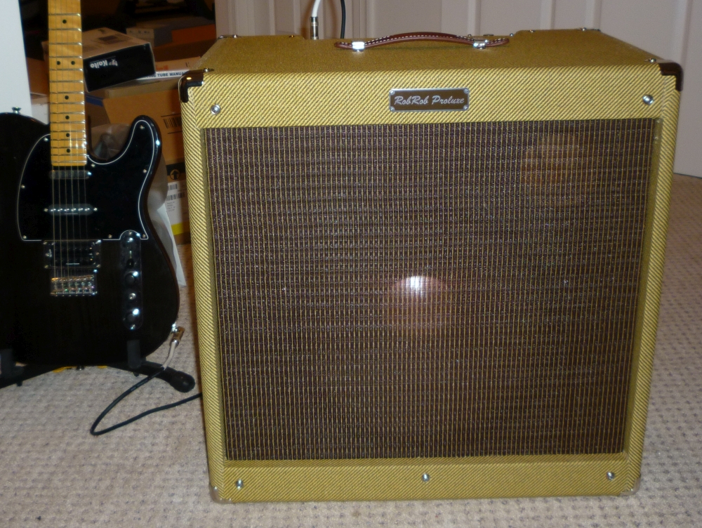
The Complete Combo Cab With 15" Hemp Cone JBL E130
Rear With Standard Open Back
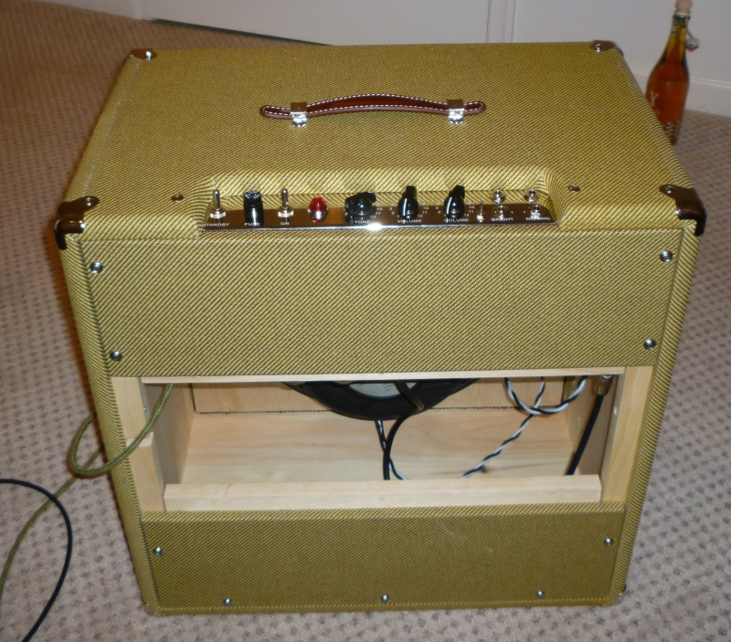
Rear Sealed For Use As Sealed TL806 Extension Cab

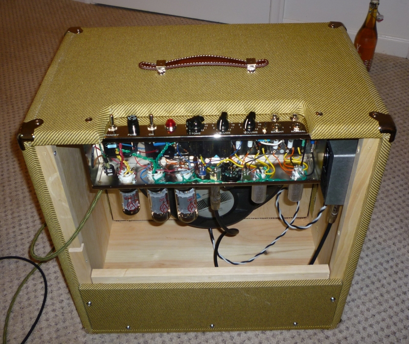
Chassis and Speaker Soak attenuator visible.
Thiele TL806 Cab With 4" x 4" Round Port & 15 Inch JBL E130 With Hemp Recone
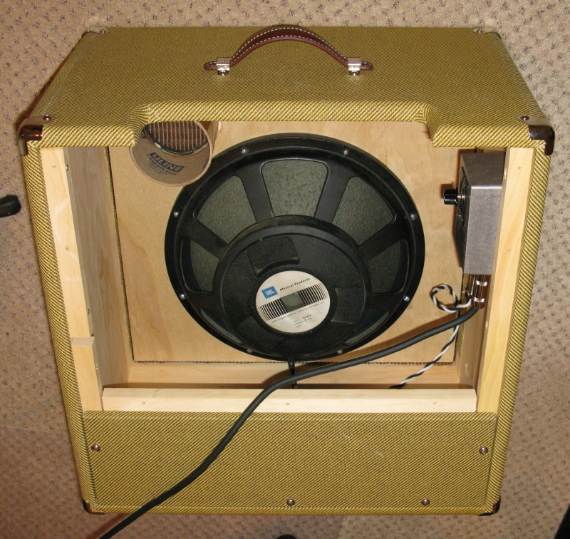
Note the cool green tint of the big 15 inch cone. The speaker is very efficient (and loud) at 105dB SPL and is rated at 300 watts. The down side with this speaker is it makes the amp very heavy and at 300 watts I don't get any speaker breakup. The up side is this amp can keep up with any drummer and is great for gigging. Carl's Custom Guitar's Speaker Soak attenuator installed at upper right to allow less-than-ear-splitting practice. See this PDF for more info on vented TL806 cabinets.
The Kit
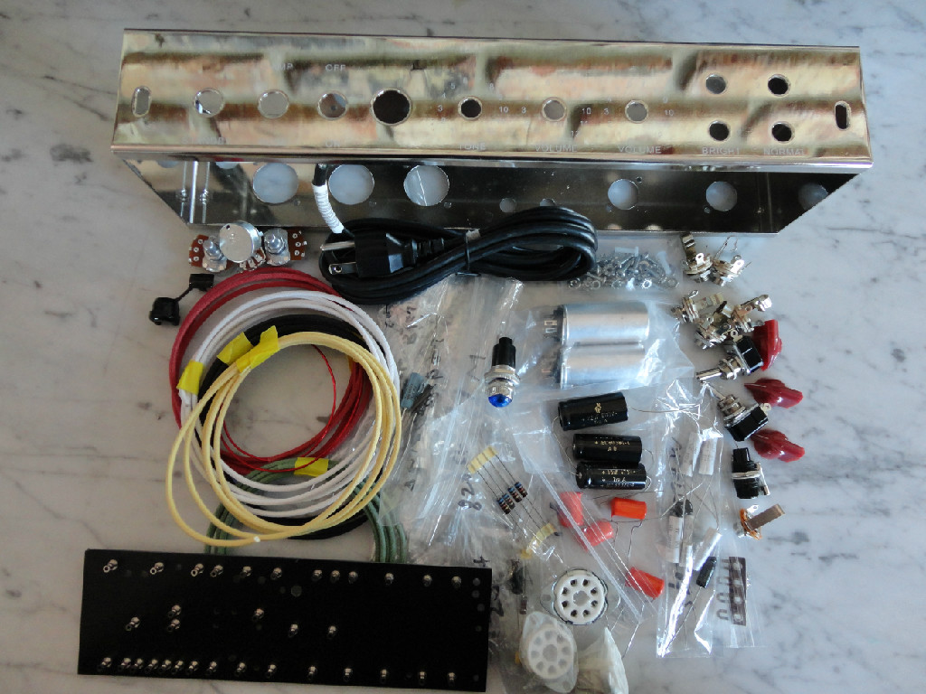
The current Boot Hill kit uses a turret board as seen here at bottom left.
WARNING
Tube amplifiers use lethal high voltages and have large capacitors that store enough electricity to kill. You MUST drain the capacitors and verify no voltage remains before disassembling the amp. Once the chassis is removed verify there is no voltage present by testing the large caps with a multi-meter in the DC volts mode. Put the meter's two probes on both ends of each cap and verify no voltage is read. Also keep in mind the tubes can be very hot.
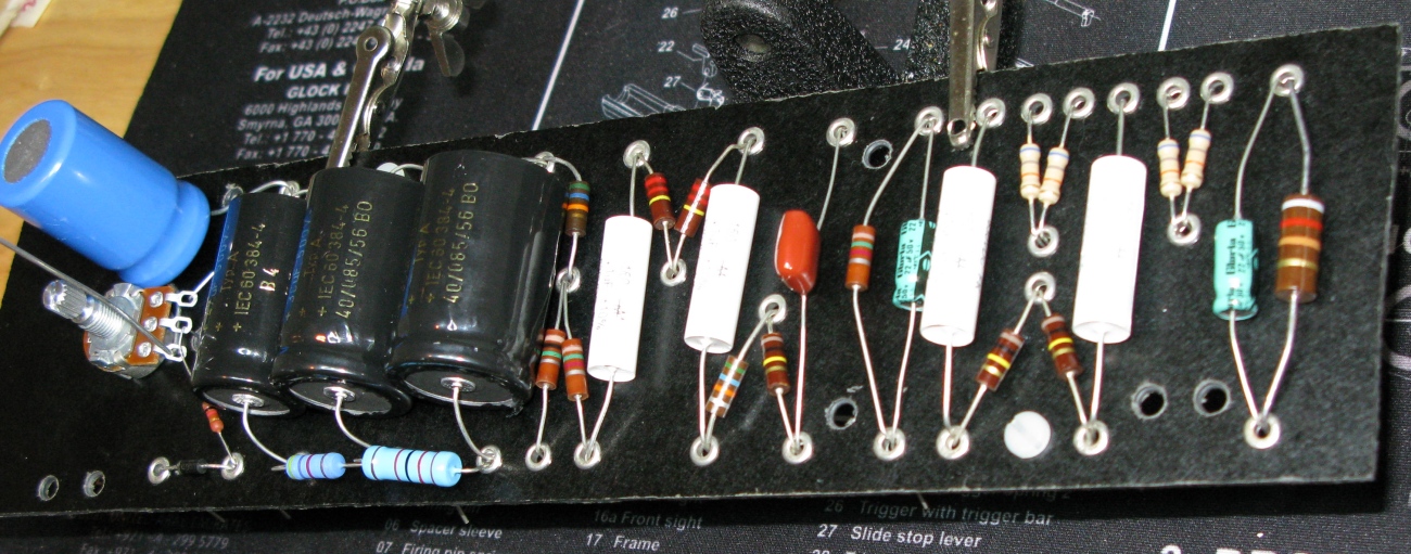
I started the build by laying out all the circuit board components following the layout diagram.
Circuit Board Laid Out (but not soldered)
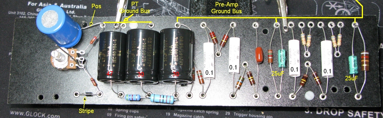
It is critical you get the big filter capacitors (center) connected properly. The 'necked down' part of the cap is the + end of the cap. Also notice the blue bias filter capacitor on the left is connected positive to ground. You must do this because it is working with negative voltage. The bias diode stripe indicates its polarity. Now would be a good time to use your multi-meter to measure all the resistors and compare them to the layout diagram to make sure you haven't mixed any of them up.
Proluxe 35 Watt Upgrade
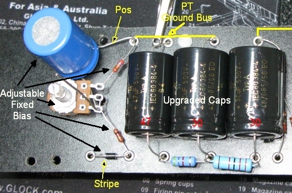
The $15 Proluxe upgrade gets you larger, upgraded filter capacitors and an adjustable fixed bias system. When combined with 6L6 power tubes, a GZ34 rectifier tube and the correct power and output transformers you get 35 watts at the speaker. The power transformer must supply 50 volts AC for the fixed bias system and the output transformer should be rated for at least 35 watts output.
Antique Electronic Supply's P-TF41316 Power Transformer (PT)
![]()
Left side (primary winding) BLACK & WHITE wires to wall power Black and White wires. Right side (secondary windings) two RED wires to Rectifier tube input. RED/YEL wire is center tap to ground, BLUE to Fixed Bias Diode, two YELLOW wires to Rectifier tube heater, two GREEN wires to all other tube heaters.
The Power Transformer converts 120v AC wall power into the four different AC voltages your amp needs to function: 660v for the tubes, 50v for the power tube bias, 6.3v for the tube heater filaments and 5v for the rectifier heater.
In retrospect I wish I had gone with a power transformer rated at 4+ amps or more for the 6.3v filament heaters like the AllenAmps.com TP40D ($95) which would be perfect for a 5E3P Proluxe. That way I would have enough power to run EL34, KT66 and KT88 power tubes. Having extra 6.3v heater current available also opens the possibility of adding tubes for reverb or tremolo. I would also have made sure the power transformer came with a 6.3v filament heater center tap. Since the kit PT did not come with one I had to install an 'artificial center tap' by connecting both 6.3v green heater wires to ground through two 100ohm 1/2 watt resistors. If you don't do this the amp will usually suffer from loud 60Hz hum.
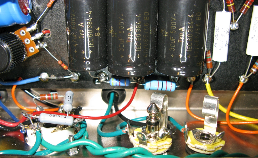
Filament Heater Artificial Center Tap
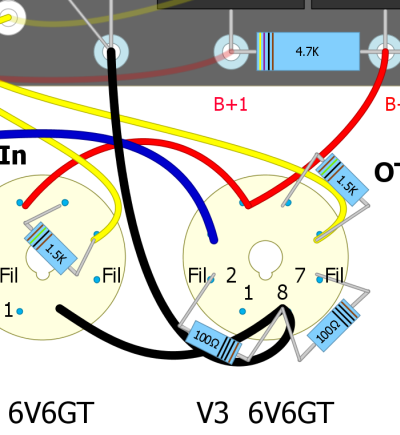
Filament heater artificial center tap consists of two 100 ohm 1/2 watt resistors connected between either power tube socket's pins 2 and 7 (heater wires) and pin 8 (cathode). This works in both cathode bias amps (elevates the heater ground) or fixed bias amps (grounded cathode). This is not required if your power transformer has a 6.3v center tap.
Hammond P-T1750J Output Transformer (OT)
Left (primary winding) Blue to 6L6GT output tube, Brown to other 6L6GT, Red to first filter capacitor or Standby Switch (≈430V DC)
Right (secondary winding) Green to Speaker Jack Tip, Black to Speaker Jack Ground, (speaker should be 4 ohm)
The output transformer takes the high voltage low amperage guitar signal from the power tubes and converts it to low voltage high amperage that a speaker needs.
Again in retrospect, I wish I had gone with an output transformer with 8 and 16 ohm speaker outputs like the Hammond P-T1760J, Allen Amps TO26 ($69) or Mercury Magnetics FBFVO-40M. Update: In May 2014 I replaced the original 4 ohm only output transformer with a Mercury Magnetics ToneClone+ FBFVO-40M output transformer rated at 50 watts with 4, 8, and 16 ohm outputs. I also added a 3-way speaker impedance switch. The Allen Amps TO26 is a good value but fixed bias 6L6GC's will saturate the core for more compression and sustain where the more expensive MM FBFVO-40M is rated at 50 watts so it has room to spare and will give maximum volume.
Going with higher output power and output transformers is a good idea and can be beneficial to the amp's tone. Mercury Magnetics is a proponent of big iron and sells big iron kits for small amps. The downside of a higher rated output transformer is you won't get the same max volume compression and sustain as the original 5E3's underrated transformer but you will get more volume and tighter bass response.
I sourced my tubes from TheTubeStore.com and TubeDepot.com went with a JJ GZ34 rectifier tube, two Sovtek 5881WXT (6L6GB type) output tubes, and two Tung Sol 12AX7 pre-amp & phase inverter (PI, sometimes called the phase splitter) tubes. [Edit: later I discovered I preferred the Tung-Sol 12AX7 and 5881 tube's tone. My 12AY7 is an ElectroHarmonix.]
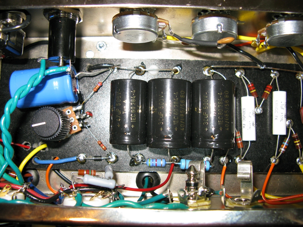
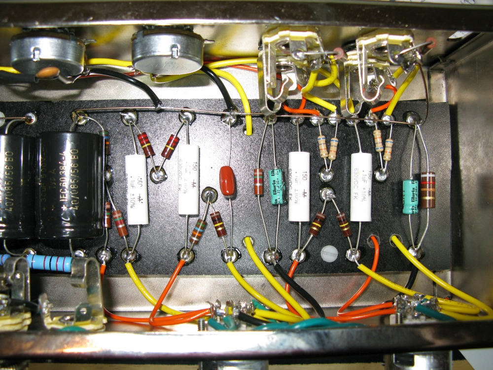
Completed Circuit Board
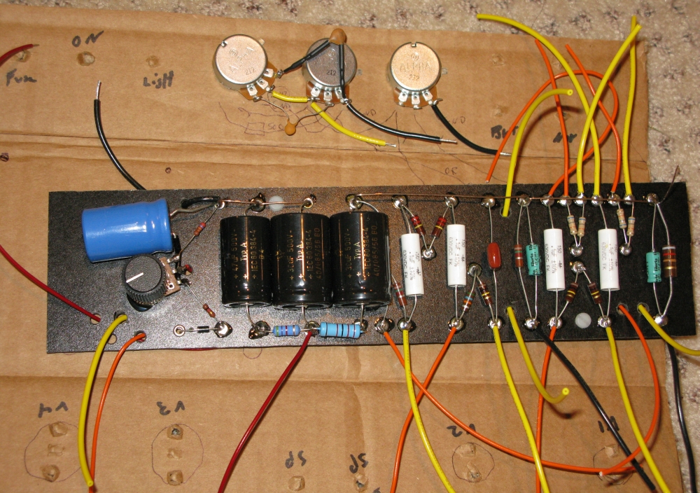
I used a cardboard template to aid in estimating wire length and wiring the volume and tone pots. I had to lay the blue bias capacitor down to clear the chassis mounted pilot lamp.
Back of Circuit Board
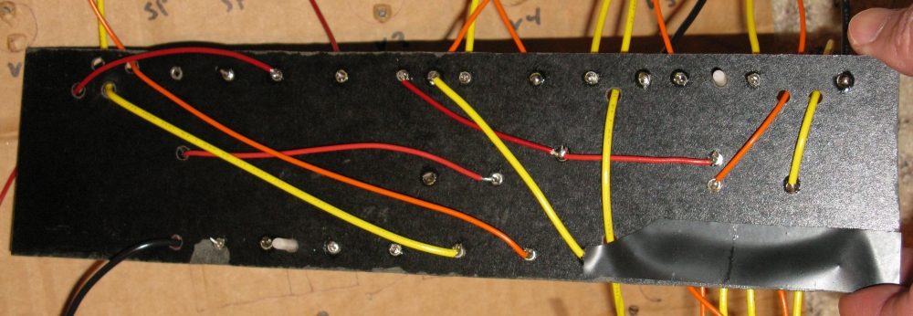
The power transformer blue wire supplies 50v AC for the fixed-bias circuit.
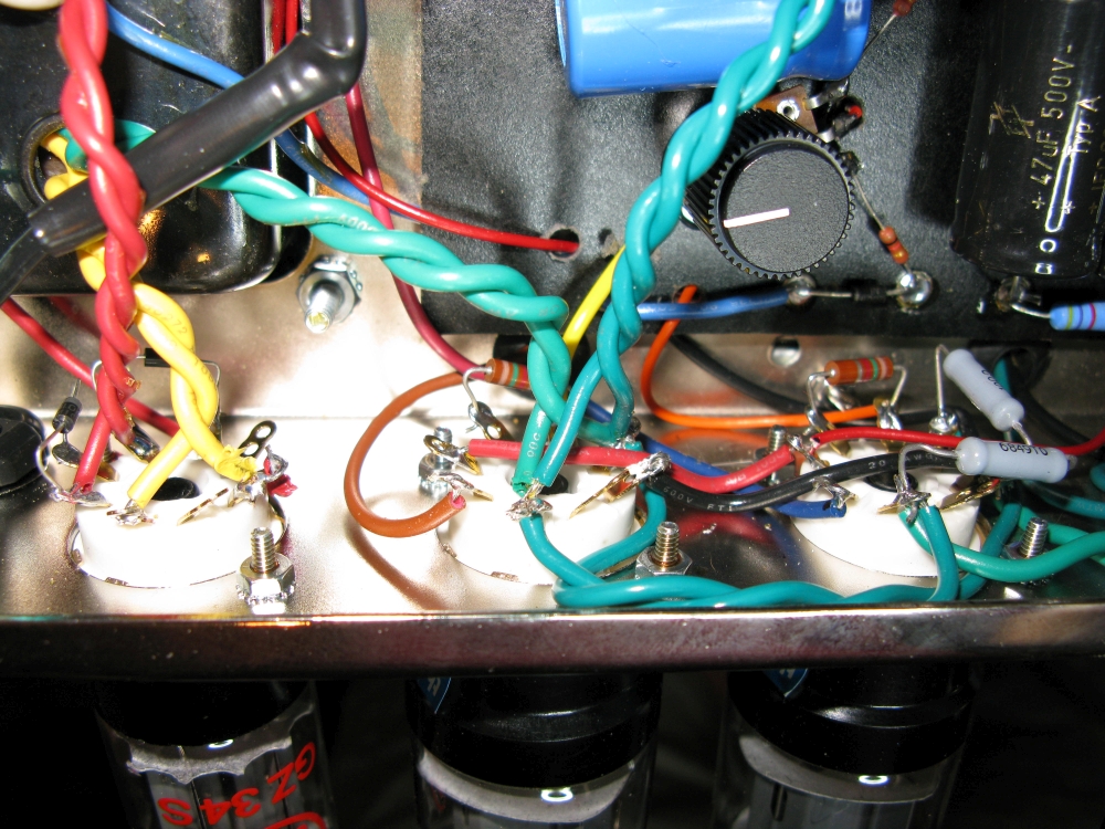
You can see the rectifier 'backup diodes' at lower left mounted on the rectifier tube socket. The 10 cent diodes extend the life of the tube rectifier and protect the amp from a failed short rectifier tube.
Grey 100ohm 1/2 watt resistors on tube V3 are the 'artificial center tap' for the tube heater circuit. They are connected from the heater terminals to the cathode terminal.
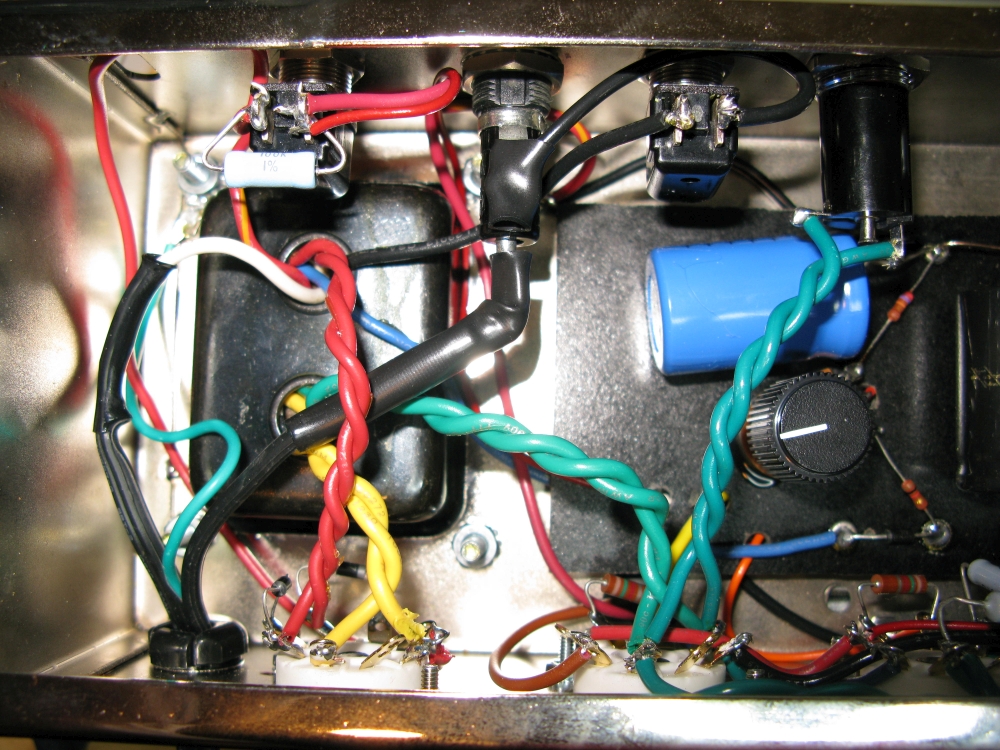
Preamp Sockets
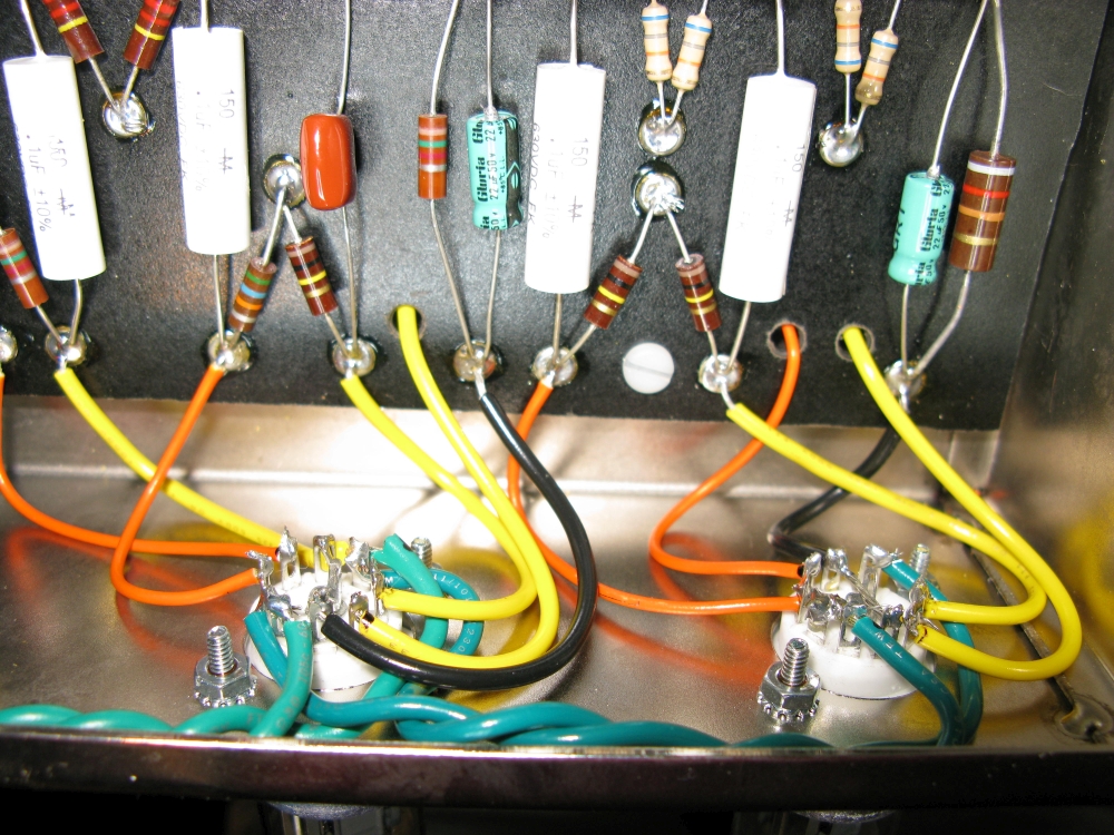
Input Jacks
Bright input jacks on the left, Normal on the right. The upper jacks are Hi and the lower are Lo (-6dB). Preamp ground bus wire is connected to the Normal - Hi input jack's ground. The other three jacks are grounded by their connection to the chassis. See How Fender Input Jacks Work for more info.
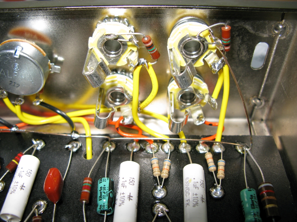
Tone, Bright Volume and Normal Volume Pots
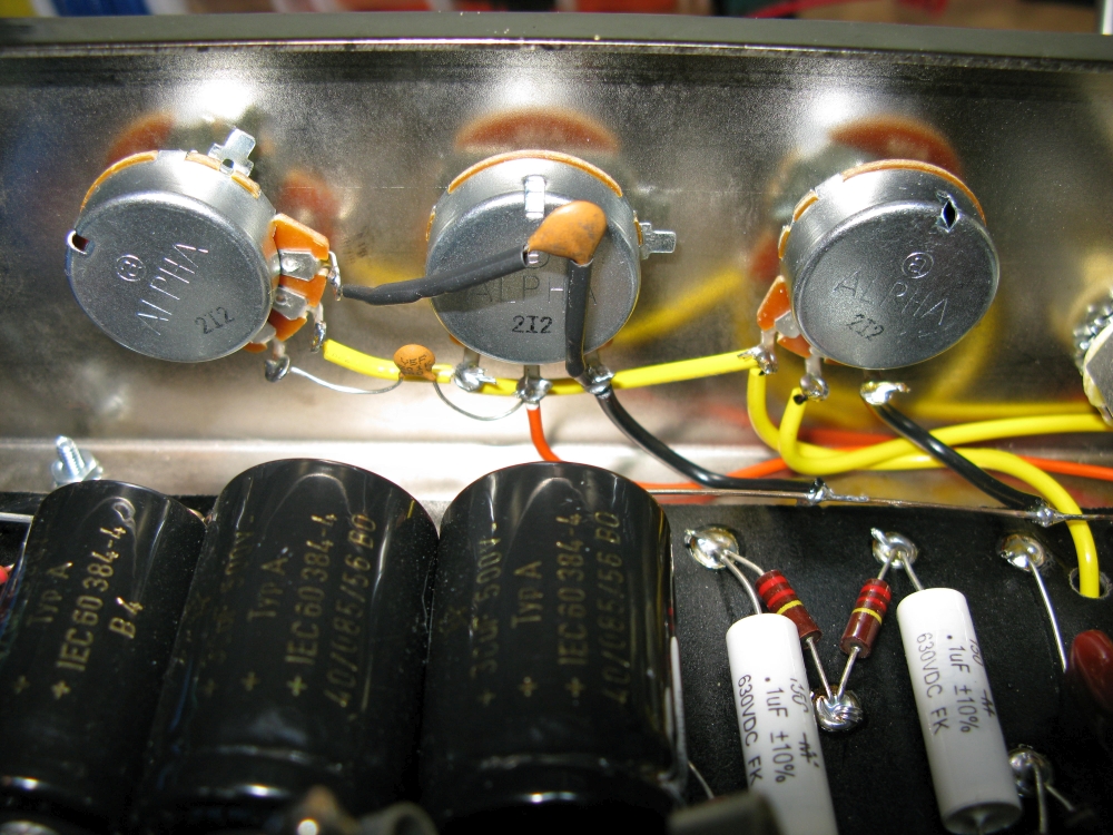
Small cap between the Tone and Bright Volume pot is the 500pF 'Bright Cap.' It bleeds high freqs around the Bright Volume pot to emphasize high freqs. The larger cap is the .0047µF tone cap which is a low pass filter that bleeds high freqs to ground.
First Power Up
I highly recommend you follow the Amp Startup Procedure when adding power to your newly built amp for the first time. Following his procedure will minimize damage from a build error. Before applying power I measured each resistor with a multi-meter and compared it to the layout diagram to make sure I didn't mix any of them up. With the Standby switch in standby I measured 345v AC on each power transformer output (red) wire with 690v AC between the two wires. This is 5% higher than the 660v the PT is rated at but not really a problem.
Always unplug your amp before working on it because the fuse and power switch terminals are always hot. Also keep in mind the amp's big filter capacitors will hold their full 400+ volt charge when no power or preamp tubes are installed. If you have to work on your amp after you power it up you will need to manually bleed down the capacitors. Once the preamp and power tubes are in they will use the capacitor power and bleed them down. But you should always use your volt meter to verify the caps are near 0 volts before putting a hand inside the amp chassis.
With all the tubes installed the power transformer's bias output measured 51v AC. The bias adjustment pot measured -65v DC at the input terminal and -40v DC out to the power tube control grids which gave me a bias setting of 38 milliamps of cathode current which is about 63% of the tube's max dissipation (70% is considered the max safe dissipation for class AB amps). 63% came at about the half way point on the bias pot.
My B+ at the Standby Switch measured 435v DC, B+2 at the second filter cap was 389v, and B+3 at the third cap was 247v. The 5881WXT Sovtek power tubes measured 430v at the plate, 389v at the screen grid and -39v of fixed-bias at the grid.
Preamp tube V1A measured 201v at the plate and 1.74v on the cathode. V1B measured 209v and 1.65v. Tube V2A measured 212v and 1.86v. Tube V2B, the phase inverter (PI) was 238v at the plate, 20.3v at the grid and 57v at the cathode.
With a 12AY7 tube in V1 I measured 148v at the V1A plate and 2.18v on the cathode. V1B measured 144v and 2.3v.
The only issue I had on first power up was I forgot to solder the volume pots' ground wires to the ground bus. The bright volume pot was a little scratchy and the tone control wasn't working and then I remembered I needed to solder those last two wires.
The amp sounds beautiful and is much, much louder than my 5 watt amps.
Standard 5E3 DC Voltages
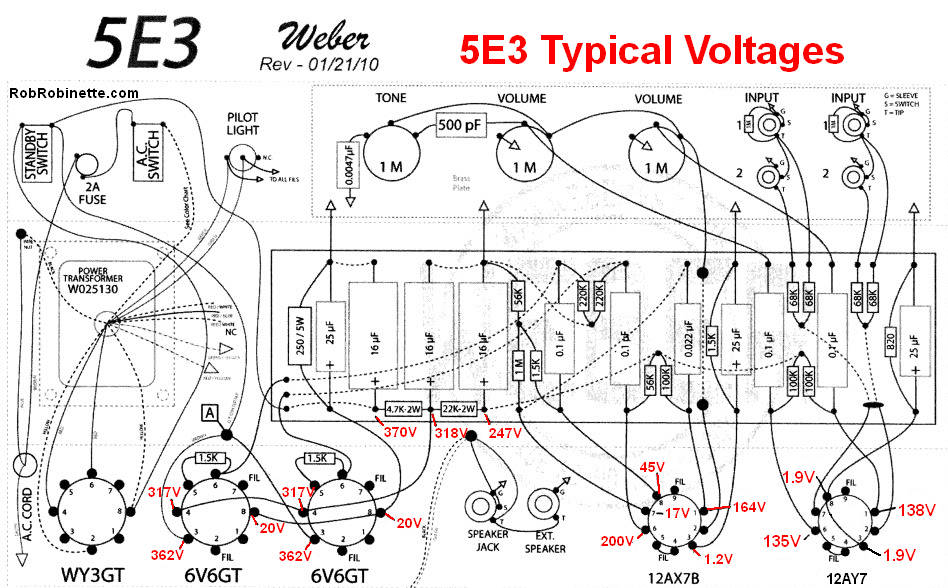
Diagram by Telenut62
Power Output Test
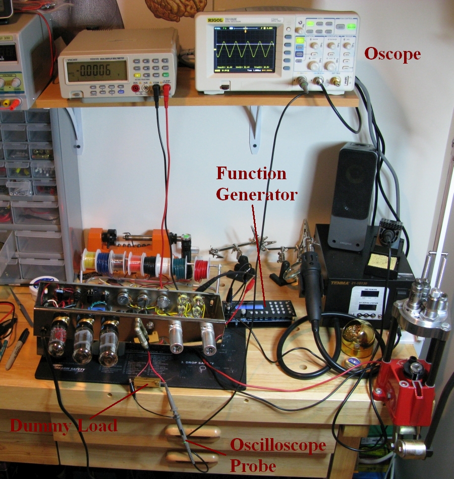
I measured the amp's power output at 35.3 watts. I used a 0.1v peak-to-peak 400Hz sine wave into the Normal Hi jack, plugged in a dummy load (4 ohm 50 watt resistor) to the speaker jack, connected my oscilloscope leads to each end of the dummy load resistor, turned up the volume until the top of the sine wave began to flatten out then backed off until the distortion went away and read the peak-to-peak voltage off the oscope of 33.6 volts. That equals 11.88v AC RMS so 11.88v^2 / 4ohms = 35.3 watts.
That's with the bias set to 63% of max dissipation. I played with the bias adjustment and watched the waveform. There's a little crossover distortion showing at 63% which gets more prominent at lower settings but I had to go to almost 80% to get rid of the crossover bulge. I didn't leave it there very long since 70% is max safe for class AB amps.
Cost
$15 Proluxe upgrade (bumps power up to 35watts with fixed-bias and 6L6 type tubes)
$15 Shipping
$70 Power Transformer shipped
$55 Output Transformer shipped
$15 Rectifier Tube JJ GZ34
$30 12AX7 Preamp Tubes Sovtek Reissue (2)
$35 5881WXT Power Tubes Sovtek matched pair
$10 Tube shipping (transformers and tubes sourced from Antique Electronic Supply)
$434 Chassis Subtotal
Finished Tweed 22" x 22" x 14" combo cab $350 + $30 shipping from TRM Guitar Cabinets. It has the JBL recommended 3.3 cubic feet of interior space and 4" x 4" round port tube. I ordered it with a three piece back so I can run it as a combo with the middle panel out for cooling or seal the cab and use it as a closed back ported extension cab.
$374 JBL E130 15" 300 watt 105dB SPL Speaker (ebay, hemp re-cone and conversion to 4 ohm, shipping)
Hemp re-cone and 4ohm conversion done by A Brown Speaker Repair
Total cost: $1188.
Troubleshooting
If your new amp has any problems check out the Amp Troubleshooting page.
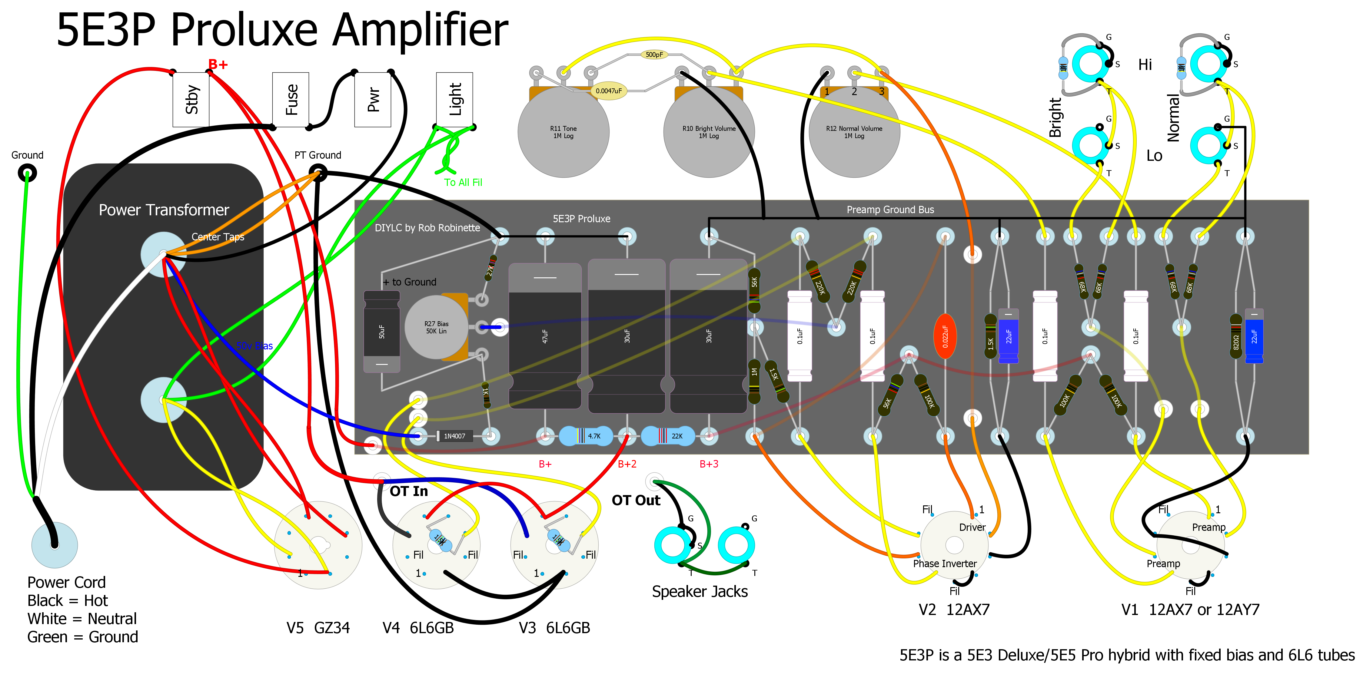
Here's the Annotated 5E3P Layout Diagram Courtesy of Weber Speakers
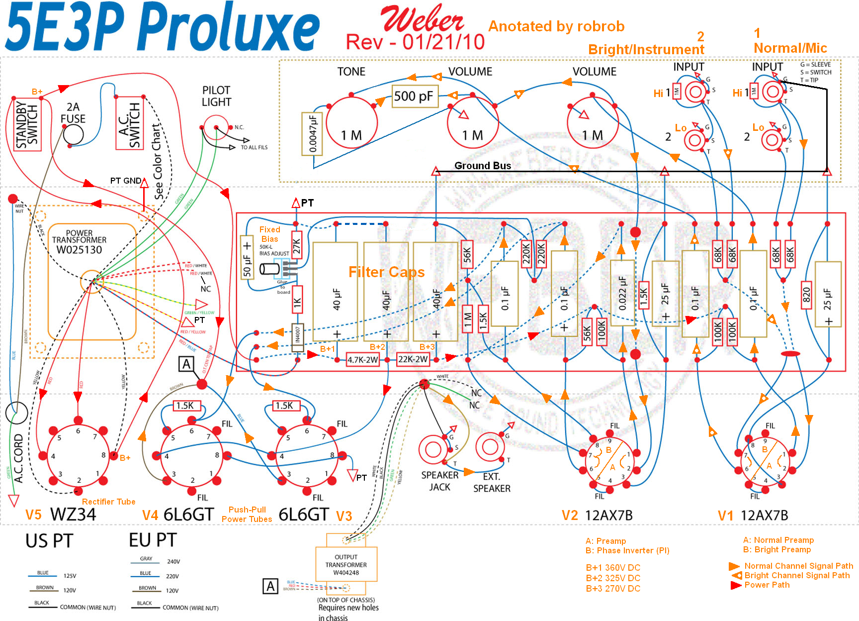
Signal flow shown with orange arrows, power flow in red arrows.
Weber 5E3P Proluxe Schematic
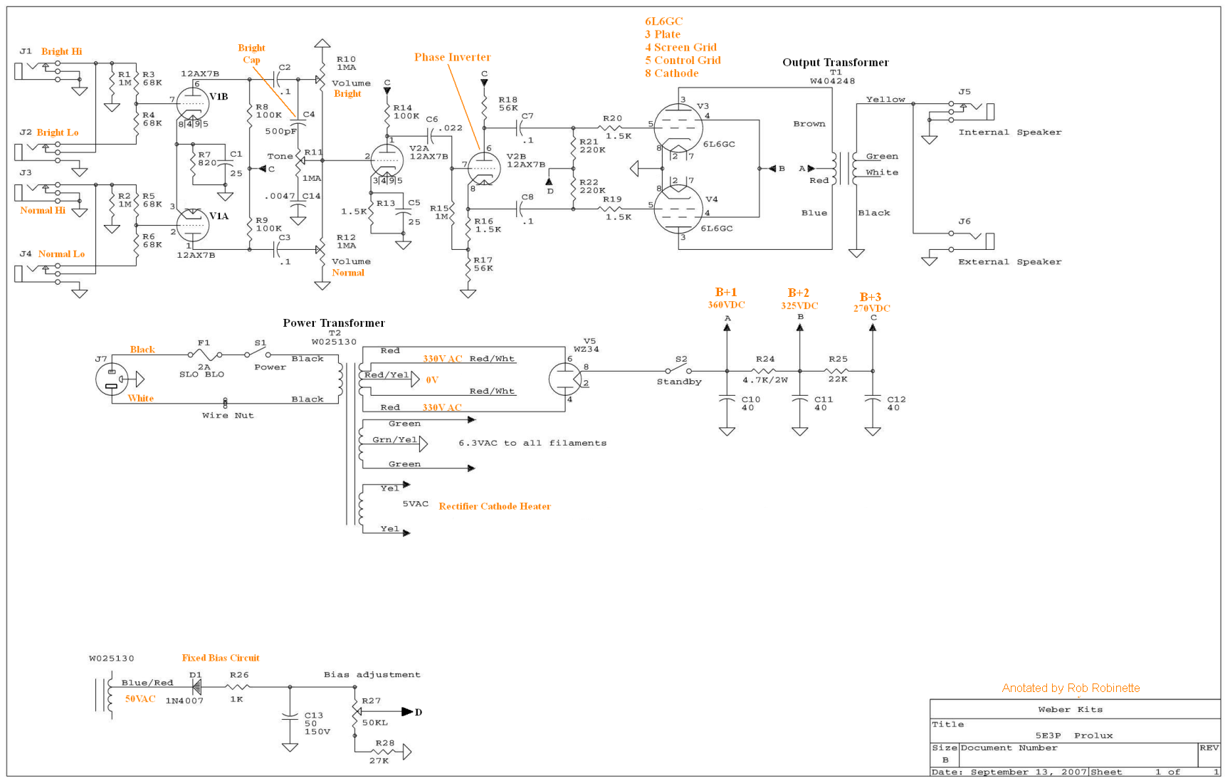
Input jacks: J1 & J2 are the 'Bright/Instrument Channel,' J1 is Hi, J2 is Lo (-6dB). Cap C4 is the 'Bright Cap' that allows high frequencies to bypass the Volume control. Cap C14 is the standard high frequency low pass filter for the tone control.
Input jacks J3 & J4 are the 'Normal/Mic Channel,' J3 is Hi, J4 is Lo (-6dB). See How Fender Input Jacks Work for more info.
5E3 Signal Flow
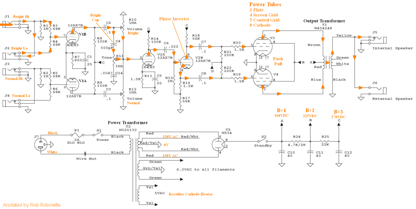
Guitar input jack at upper left, speaker jack at upper right.
5E3P Proluxe DIYLC Layout Creator File
Download the 5E3P Proluxe DIYLC file here: 5e3p_Tube_Guitar_Amplifier.diy
Download the standard 5E3 Deluxe file here: 5e3_Tube_Guitar_Amplifier.diy
Turret Wiring Strain Relief
Mil Spec Turret Board Strain Relief
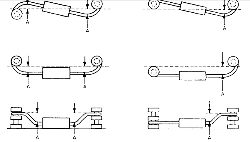
You need some bend in your component leads to allow for expansion and contraction during amplifier heat cycles.
Setting the 5E3P Power Tube Bias
WARNING: The 5E3 amplifier chassis contains lethal high voltage--over 700 volts AC and 360 volts DC. If you have not been trained to work with high voltage then have an amp technician adjust the amp's bias. Never touch the grounded chassis with one hand while probing with the other because a lethal shock can run between your arms through your heart. Use just one hand when working on a powered amp.
All of the bias measurements below were done using a Fluke 87 multimeter.
Measure Bias With the Output Transformer Resistance Method
The quiescent (idle or no signal) plate current can be calculated by measuring the output transformer's resistance and voltage drop between the output transformer's center tap and both power tube plates. This "transformer resistance method" is my recommended bias measurement method is just as accurate if not more so than directly measuring the current using the "output transformer shunt method" (detailed in the next section) and it is much safer.
Measurement Overview
1. With a warm amp measure the output transformer center tap voltage and power tube plate voltages.
2. Subtract the plate voltage from the center tap voltage to get the output transformer voltage drop.
3. Turn off the amp and measure the resistance from the center tap to the power tube plates.
4. Divide the voltage drop by the resistance to get the bias current.
Measure and record the plate voltage, voltage drop between the center tap & both power tube plates and the resistance between the center tap & both plates. You only have to measure the resistance once for the life of the transformer.
1. The first step is with the amp off clip the multimeter ground probe to a good ground. I recommend using the power transformer center tap ground connection. Doing this will allow you to use only one hand to safely take high voltage measurements.
With the ground probe clipped turn on the amp (standby switch too) and let it warm up for a few minutes. When warm measure and record the plate DC voltage on both of the power tubes' pin 3. Pin 3 is connected to the output transformer. This will be high voltage DC at 350 to 500 volts. Do not allow the multimeter probe to make contact with the adjacent socket pins.
2. Next we measure the output transformer voltage at the center tap. The standby switch is directly connected to the center tap so you can measure its voltage there. Record the voltage values down to three decimal places. You then subtract the plate voltage from the center tap voltage to get the voltage drop. This is the voltage drop through half the transformer. You can also measure the voltage drop directly by putting your meter probes on the plate and center tap.
3. Turn the amp off and ensure the filter capacitors are discharged then measure the output transformer resistance between the same two spots as above -- the center tap and both tube plate pins. You want to do this with the output transformer still warm to get the most accurate reading. You only have to measure the transformer resistance once for the life of the transformer so write down the resistance and use it for all future bias setting sessions.
4. Next we divide the voltage drop by the ohm reading to get the plate current in amps.
Example: When I measured these values on my 5E3 Deluxe I got:
Tube V3: 1.347 volt drop and 72.0 ohms between the standby switch and plate = 1.347 / 72.0 = .0187 amps or 18.7 milliamps
Tube V4: 1.325 volt drop and 80.7 ohms = 1.325 / 80.7 = .0164 amps or 16.4 milliamps
I used my Fluke 87 multimeter to compare this bias method with directly measuring the bias current using the "transformer shunt method" (described below in next section) and got results within 1 milliamp.
With the plate voltage and milliamp values go to my Tube Bias Calculator. Select your tube type, enter the plate voltage and click a Calculate button. The 5E3P is a Class AB Fixed Bias amp so 70% of max dissipation is your safe limit. Go down to the Tube Dissipation Using Plate Current section and plug in your plate current milliamp values and hit any Calculate button to see what % of max dissipation you are running. I usually set my amps around 70% unless a lower setting sounds better--yes play your amp after every bias change as you may find you prefer a cooler bias setting. Fender tended to bias their push-pull tweed amps cool from the factory at around 50 to 60%.
Make small changes when adjusting the bias pot and measure the plate voltage and plate current again. You have to measure the voltage each time because the voltage and current will change with a bias pot change.
Setting a higher % of max dissipation will make the bias 'hotter.' The power tube grid voltage is always negative on fixed bias amps and a hotter bias will have the grid voltage closer to zero. A hot bias for the 5E3P would be around -44V DC. Setting a lower % of max dissipation will make the bias 'cooler' and the grid voltage will be a larger negative number like -50V.
For my Tung-Sol 5881 power tubes rated at 26 watts of max dissipation I ended up with 448v on the plates and 40.0 milliamps of plate current which equals 69% of max dissipation with 70% (40.6ma) being the max safe dissipation for fixed bias Class AB amps. The grid voltage was -45.1V DC (yes, a negative voltage). When running a 5Y3 rectifier and 6V6GT power tubes the plate voltage was 367v with 18.7 milliamps of plate current for 6.9w of dissipation (max is 12w) for 57.2% of max.
Measure Bias With the Output Transformer Shunt Method
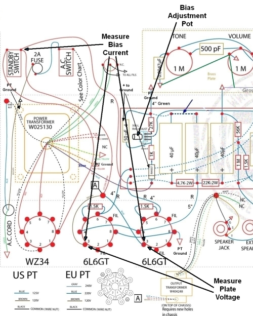
Bias measuring points using the Output Transformer Shunt Method. Bias current is measured between the Standby Switch (Output Transformer center tap) and the power tubes' pin 3 (measure both power tubes). Plate voltage is measured between the power tubes' pin 3 and ground. Turning the bias adjustment pot counterclockwise reduces cathode current and dissipation.
Another method used to measure bias is the output transformer shunt method. This method has you directly measure the power tube plate current but it is much more dangerous than the previous method for reasons you'll see below. Another reason to avoid this method is typically milliamp measurement is less accurate than volts and ohms for most multimeters.
The first step is to measure and record the plate DC voltage on both of the power tubes' pin 3. Pin 3 usually has a blue or brown wire coming from the output transformer. The voltage should be between 420v to 460v DC.
Then set your multimeter to measure DC milliamps. This usually involves moving the meter's red probe to another socket. Some meters require you to push a button to set DC or AC, make sure you're measuring DC current. If you have two multimeters use the best one to measure DC current and the other to measure DC voltage.
WARNING: When measuring milliamps (current) as soon as either meter probe makes contact with a voltage that same voltage passes through the meter to the other probe--both meter probes will be hot with high voltage so you must control both probes carefully. You must wear safety glasses because if a meter probe accidentally contacts a grounded component an arc will occur and molten metal will spray out from the arc. This procedure is dangerous and if you are not trained for working with high voltage I recommend you take your amp to a professional tech.
Place one probe on either power tube's pin 3 (plate). The other meter probe now has over 400v DC on it so be careful as you place it on a standby switch terminal (the standby switch is connected directly to the output transformer's center tap) and read the plate current in milliamps. Carefully do the same for the other power tube's pin 3. Be careful not to make contact with anything as you remove both meter probes from the amp chassis.
With the plate voltage and milliamp values go to my Tube Bias Calculator. Select your tube type, enter the plate voltage and click a Calculate button. The 5E3P Proluxe is a Class AB Fixed Bias amp so 70% of max dissipation is your safe limit. Go down to the Tube Dissipation Using Plate Current section and plug in your plate current milliamp values and hit any Calculate button to see what % of max dissipation you are running.
By Rob Robinette
References
RCA Corporation, RCA Receiving Tube Manual, RC30.
Merlin Blencowe, Designing Tube Preamps for Guitar and Bass, 2nd Edition.
Merlin Blencowe, Designing High-Fidelity Tube Preamps
Morgan Jones, Valve Amplifiers, 4th Edition.
Richard Kuehnel, Circuit Analysis of a Legendary Tube Amplifier: The Fender Bassman 5F6-A, 3rd Edition.
Richard Kuehnel, Vacuum Tube Circuit Design: Guitar Amplifier Preamps, 2nd Edition.
Richard Kuehnel, Vacuum Tube Circuit Design: Guitar Amplifier Power Amps
Robert C. Megantz, Design and Construction of Tube Guitar Amplifiers
Neumann & Irving, Guitar Amplifier Overdrive, A Visual Tour It's fairly technical but it's the only book written specifically about guitar amplifier overdrive. It includes many graphs to help make the material easier to understand.
T.E. Rutt, Vacuum Tube Triode Nonlinearity as Part of The Electric Guitar Sound
[ How Amps Work ] [ Overdrive ] [ 5E3 Mods ] [ 5F6A Mods ] [ AB763 Mods ] [ DRRI & 68 CDR Mods ] [ How the 5E3 Deluxe Works ] [ How the AB763 Works ] [ AB763 Models ] [ Tube Bias Calculator ] [ Amp Troubleshooting ] [ Deluxe Models ] [ Deluxe Micro Amp ] [ Bassman Micro Amp ] [ Champ Micro Amp ] [ My 5E3 Build ] [ Reverb & Tremolo ] [ SixShooter ] [ Spice Analysis ] [ VHT Special 6 Ultra Mods ] [ Telecaster Mods ] [ Android Tube Bias Calculator App ] [ The Trainwreck Pages ] [ Fender Input Jacks ] [ B9A Prototype Board ]