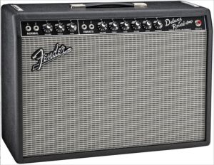
AB763 Blackface Amp Modifications
Includes modifications for the 65 Deluxe Reverb Reissue and 68 Custom Deluxe Reverb
By Rob Robinette
WARNING: A tube amplifier chassis contains lethal high voltage even when unplugged--sometimes over 700 volts AC and 500 volts DC. If you have not been trained to work with high voltage then have an amp technician service your amp. Never touch the amplifier chassis with one hand while probing with the other hand because a lethal shock can run between your arms through your heart. Use just one hand when working on a powered amp. See more tube amplifier safety info here.
'AB763' was Fender's internal model designation for the 1963 blackface circuit. The "763" in the model name comes from the circuit change date of 7-1963. It was used in the Deluxe Reverb, Twin Reverb, Super Reverb, Concert, Band-Master, Showman, Pro, Vibrolux, Vibroverb, Tremolux and no-reverb Deluxe. For information about the AB763 model differences see this. The AB763 circuit is considered by most to be the pinnacle of Fender amplifier design. This is why so many post-AB763 amps were "blackfaced" back to AB763 specs. I usually prefer switchable mods that keep the amp's original tone in place. The often unused Normal channel is also a great place to mod away with to make that channel interesting and usable.
If you are considering building an AB763 with reverb in a head cab I recommend you go no smaller on the head cab dimensions than the silver face Dual Showman Reverb head cab. It allows for enough separation of the reverb tank and power transformer to keep hum pickup to a minimum. There's also enough room for the addition of a nice little 6" practice speaker.
AB763 Model Differences
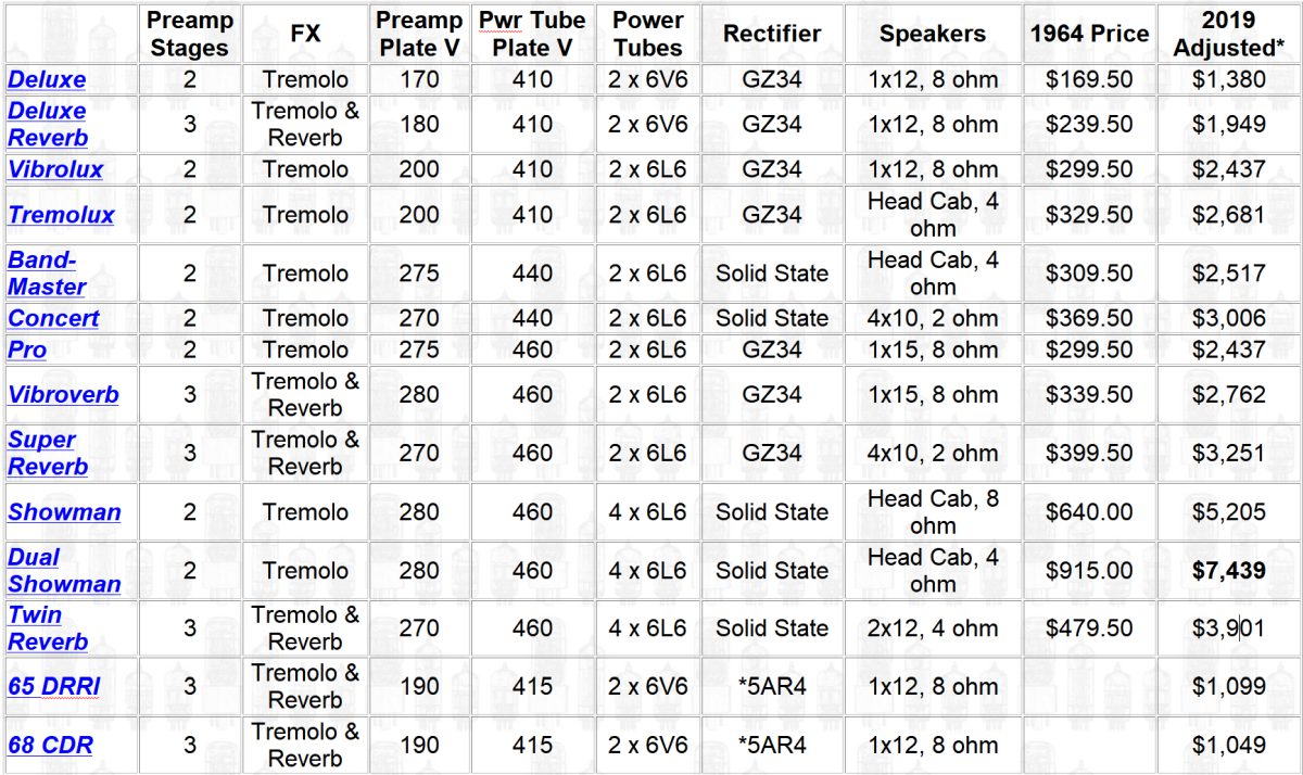
Note the Preamp Plate Voltage difference between the Deluxe Reverb and the higher powered amps.
List of Mods
robrob Normal Channel Reverb Mod The preferred way to apply reverb and tremolo to both channels and allow channel jumpering.
Fender Normal Channel Reverb Mod Apply reverb and tremolo to both channels the way Fender did it in the 68 Custom Deluxe Reverb.
"Fritz" Mod Classic mod to send both channels through the reverb and tremolo effects.
Lead Channel Mod Do something constructive with your unused Normal channel.
Plate Load Resistor Mod Add preamp gain with a simple resistor swap
Boost Preamp Voltage Add preamp clean headroom to the low voltage Deluxe, Deluxe Reverb, Vibrolux and Tremolux amps.
3-Way Negative Feedback Switch Mod Make your amp more versatile.
Master Volume Mod Add a simple Trainwreck Type-3 PPIMV master volume.
Master Volume Trainwreck Type-2 PPIMV
Master Volume + Vox Tone Cut Master volume AND late-in-the-circuit tone control. I love this thing.
1/4 Power Switch Dump 3/4 of the amp output for lower volume
10% Power Switch Dump 90% of the amp output for true bedroom level output
10% Power Jack Use your Aux jack as a 10% output jack
10% Power In External Box External box goes between your amp and speaker to dump 90% of amp power
1/2 Power Switch Pentode / Triode Switch Cut power tube output for lower volume
Add a Presence Control Use this late-in-the-circuit tone control to tame ice pick and tweak your tone.
Turn Presence Control Into Variable NFB Presence Control or Variable NFB at the flick of a switch.
Add a Mid Tone Pot If you amp doesn't have one then add one
Raw Switch Mod Eliminate the tone stack and boost volume.
Tone Stack Mods Why have two identical tone stacks? Mod one of them.
Firm Up the Deluxe and Deluxe Reverb's Loose Low End Make it sound more like a Twin Reverb.
Tremolo Cut Switch Mod Add preamp gain with this simple and very useful mod.
Slow the Tremolo Slow is good.
Stop Tremolo Ticking Simple one cap fix.
Always On Tremolo Plug Leave your tremolo footswitch at home.
Adjust Reverb Level Mod Want to change the action of the reverb control? This is how.
Reduce Ice Pick Highs Take the edge off your tone with a single cap.
Channel Mixing Resistors Bright Cap Mod Get a little more brightness from either channel.
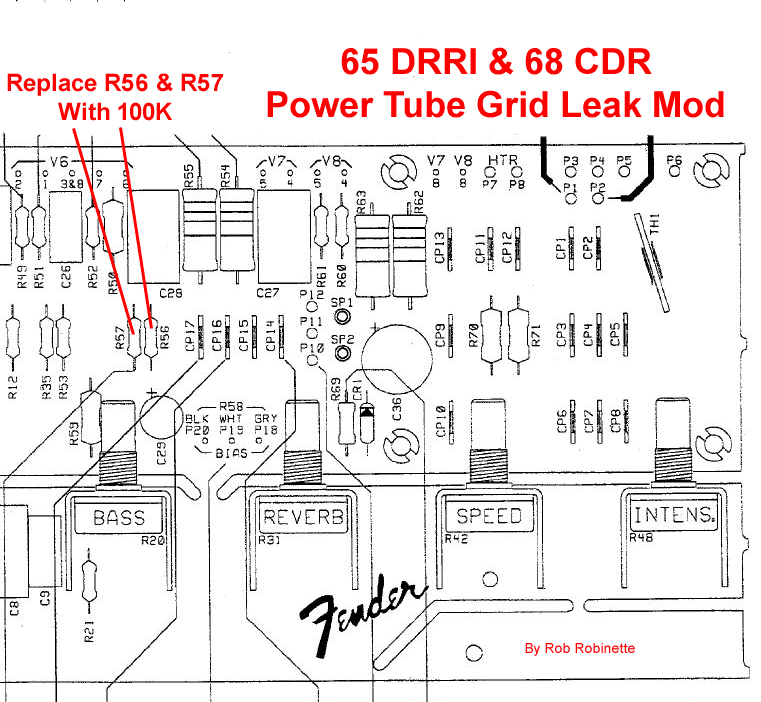
Power Tube Grid Leak Mod Marshall style 100k Grid Leak resistors.
Extra Bias Filter Cap Mod Reduce hum from the bias circuit.
Reduce Resistor Hiss Mod Swap out those noisy carbon comp resistors.
Reduce Reverb Noise & Oscillation Simple mod to clean up the reverb.
Darken the Reverb Tone Is your reverb tone too bright? This easy mod can tune the tone.
Replace the 2-Prong AC Receptacle With a 3-Prong Use modern accessories with the amp.
Convert a 65 Deluxe Reverb Reissue to a 68 Custom Deluxe Reverb
Quad Power Tube Half Power Switch Kill two of your four power tubes at the flip of a switch.
Run 6V6 Power Tubes in a 6L6 Amp Less output power, small bottle tone with more power tube distortion.
Run 6L6 Power Tubes in a 6V6 Amp A tone change with little power gain.
Run 2 Power Tubes in a 4 Power Tube Amp Cut your output power almost in half.
Run 2 6V6 Power Tubes in a 4x6L6 Amp Cut your big amp's power by 65%.
Tube Tweaks It's surprising how much you can do with simple preamp tube swaps.
"Blackface" a Silverface Amp Make your Silverface amp sound right.
AB763 Amp With Tremolo Deleted Keep the reverb but drop the tremolo.
Convert a Silverface Amp's Bias Balance circuit to Adjustable Bias + Bias Balance
Annotated AB763 Schematic & Annotated AB763 Layout Circuit study aids.
65 Deluxe Reverb Reissue Schematic and Layout
68 Custom Deluxe Reverb Schematic and Layout
AB763 Annotated Schematic
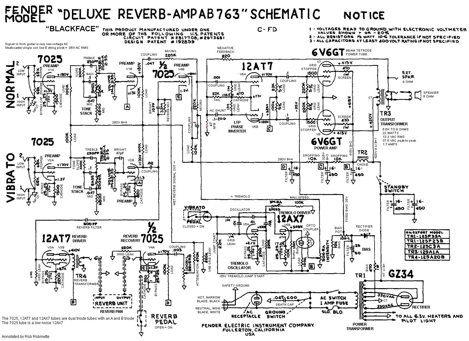
Click the image for the full size schematic. Every component function is listed.
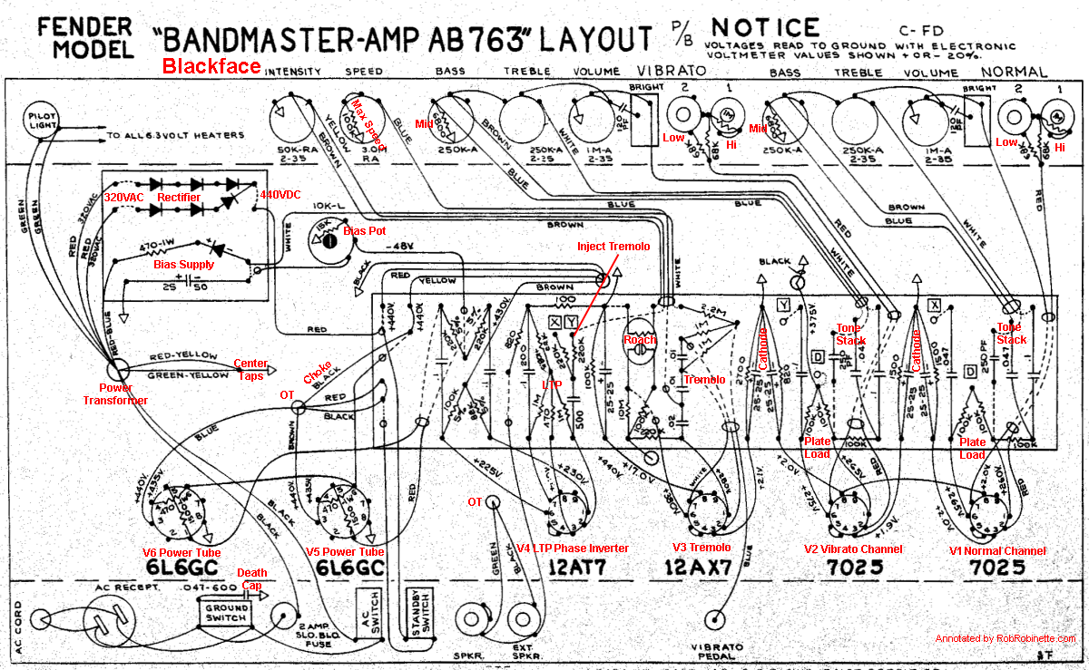
AB763 Layout Created With DIYLC
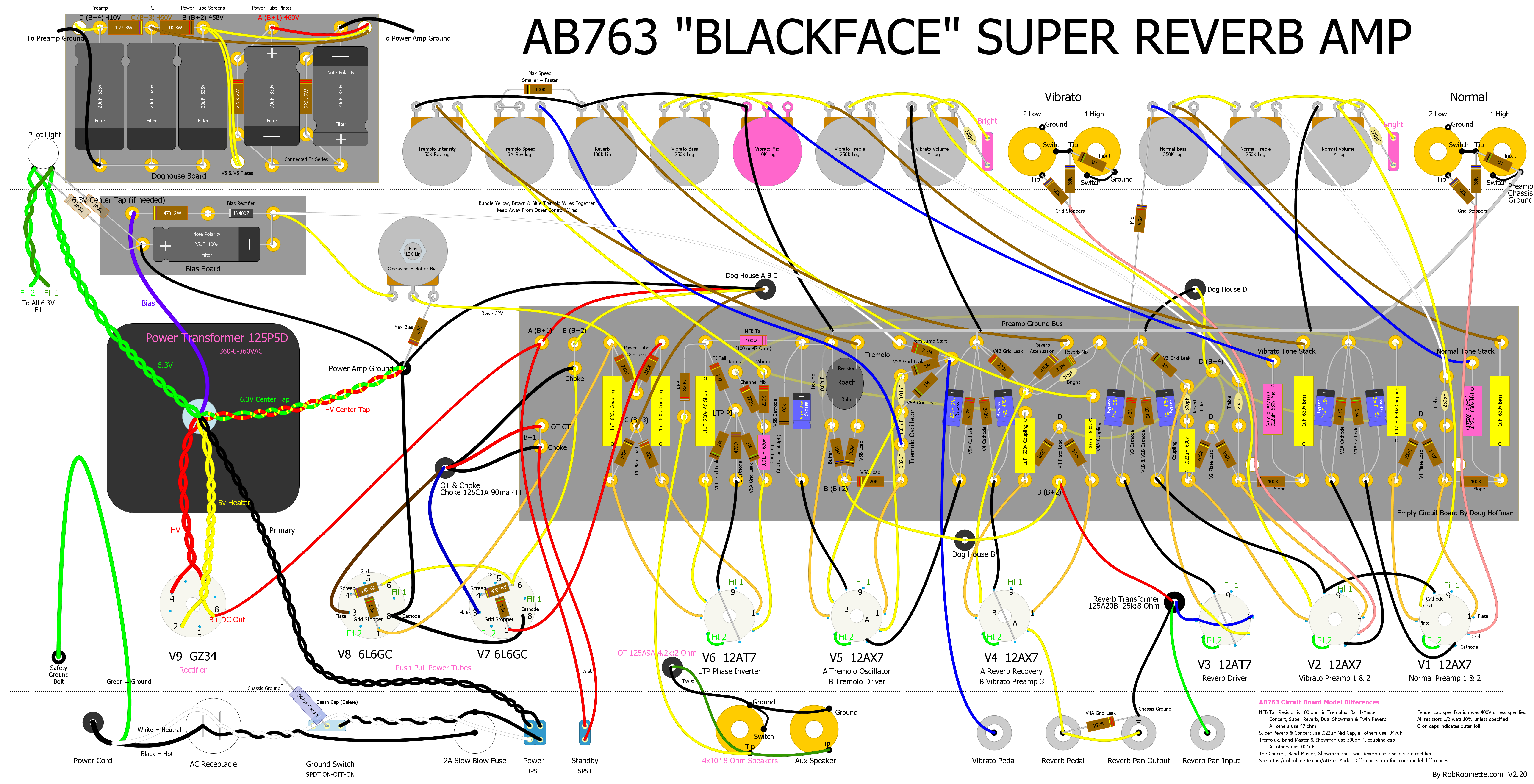
Model differences are highlighted in pink. Click on the image to see the full size layout. Download the pdf here. Download the AB763 DIYLC file here.
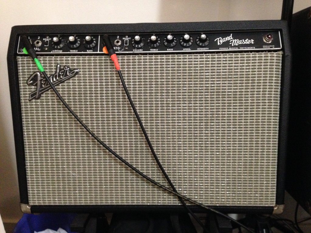
Band-Master Chassis
Fender Wire Routing
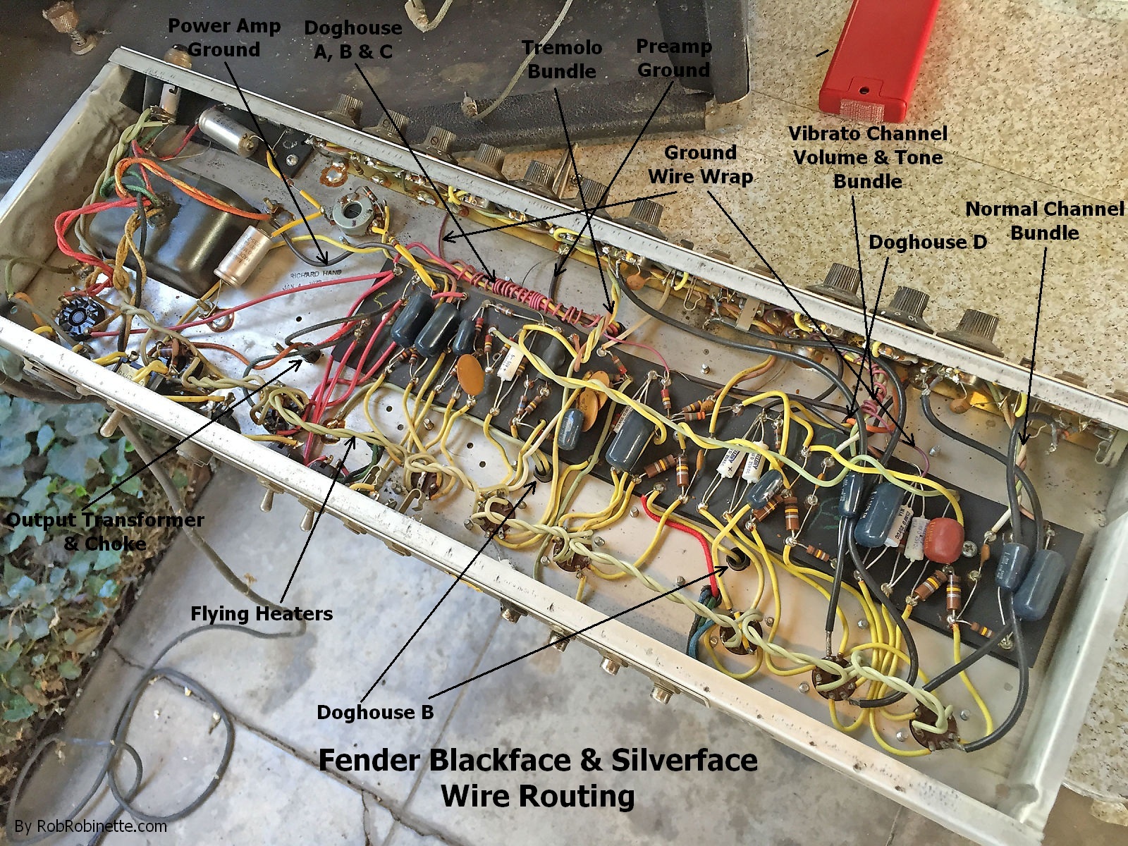
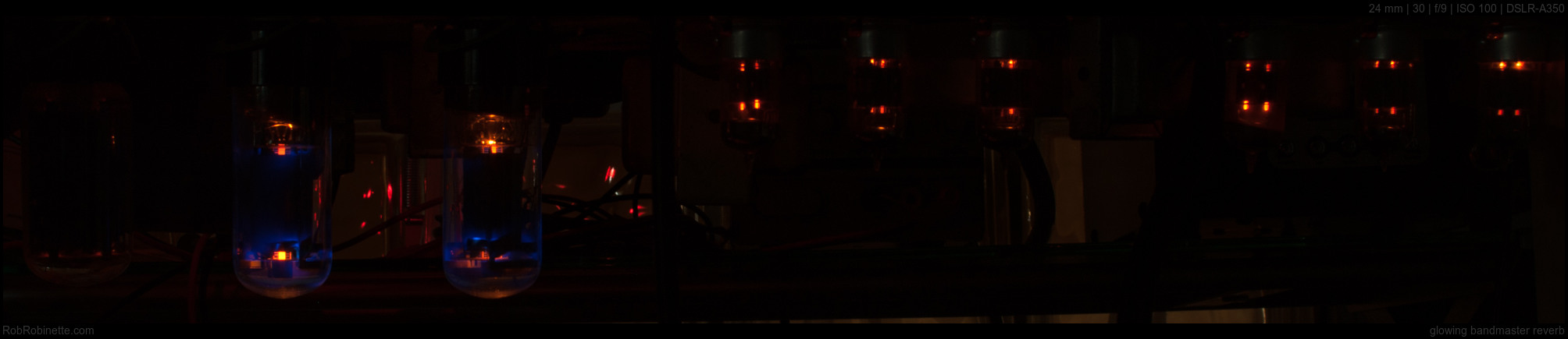
Note the two wire bundles that are wrapped with a reddish ground wire. The Vibrato channel tone wires are wrapped and the Doghouse A, B & C power wires are wrapped. This was done as a "poor man's shield". Also notice how all the Tremolo wires are bundled and run along the chassis and then shoot straight down to their terminals. The tremolo wires carry a very strong signal that can bleed into other signal wires so pay close attention to their placement. This is my personal AA1069 silverface Bandmaster Reverb and it's a very quiet amp. Silverface amps used shielded coax for the input jack and volume output runs to the V1 and V2 grids. The coax is grounded only on the input end to prevent a ground loop.
Fender Modern Hand Wired Custom 64 Deluxe Reverb
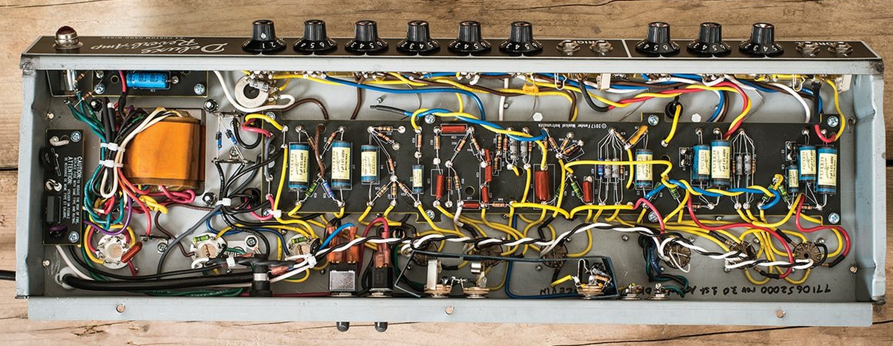
This is how Fender does a modern hand wired blackface amp. Note the use of quiet metal film resistors except the V3 2.2k cathode resistor. The "Fender Normal Channel Reverb Mod" is the blue wire that runs from the V1B plate resistor to the V2B plate resistor (blue wire twisted with yellow plate power supply wire). The small board at far left adds a soft start thermistor and Class X RFI noise cap to the mains line. Artificial 6.3v heater center tap resistors are connected to the pilot light at far upper left. The Power switch switches both the mains hot and neutral lines. The Ground Switch and AC Receptacle have been deleted. This amp has both channels run through the reverb circuit and uses bias vary tremolo instead of AB763 signal tremolo. The Custom 64 Deluxe Reverb currently sells for $2500 at Sweetwater.
Marcus Albrecht's Deluxe Reverb Build
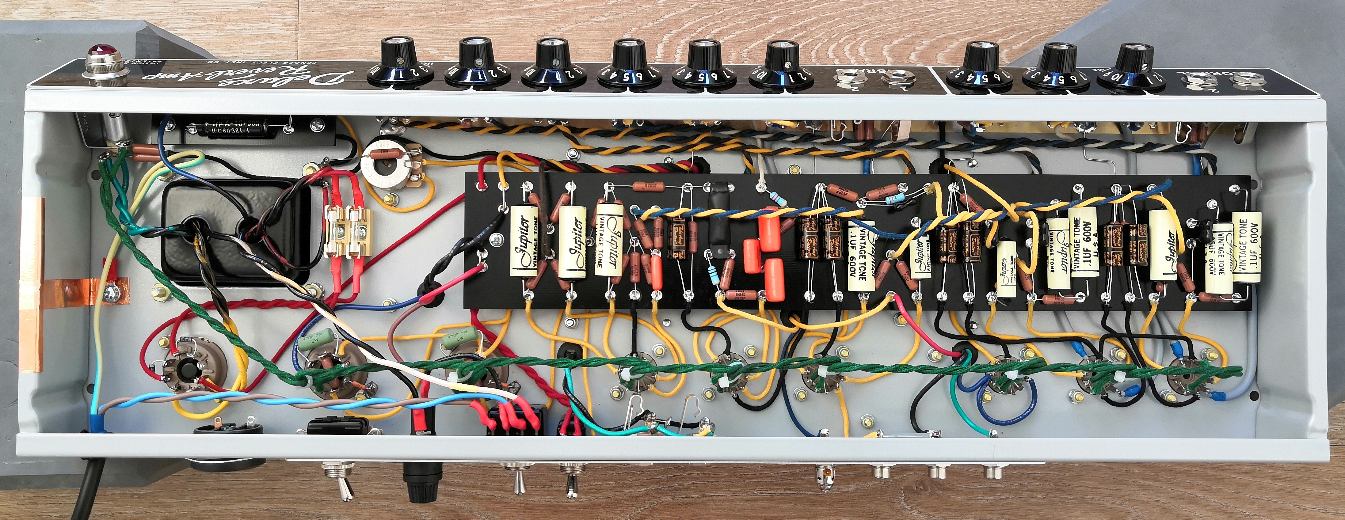
This is a beautiful build. Click the image to see the high resolution picture. Marcus is quite the photographer too.
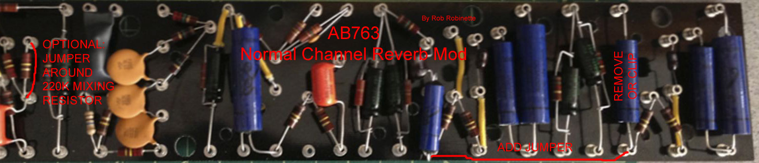
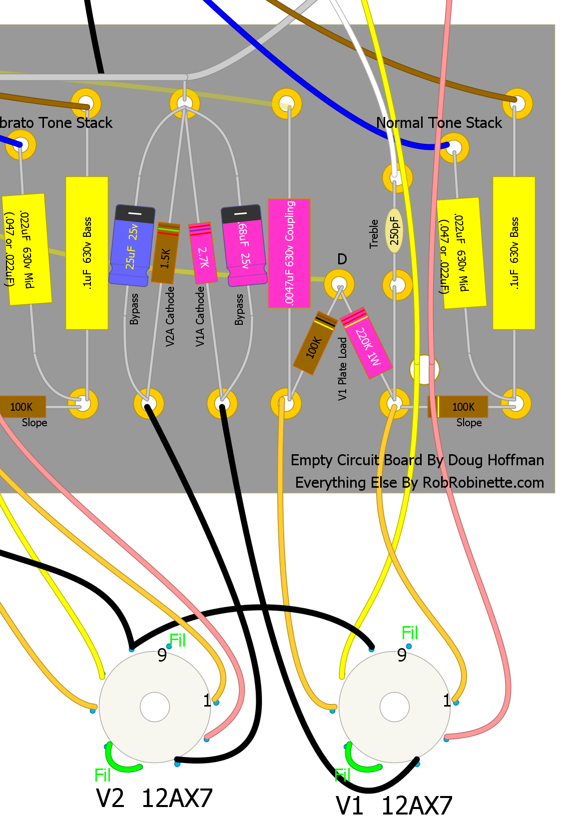
robrob Normal Channel Reverb Mod
This is my recommended mod to add reverb and tremolo to the Normal channel in blackface and silverface amps. Using this method we join the two channels using their own coupling caps and mixing resistors in a relatively noninvasive way. With each channel using a coupling cap and mixing resistor to feed the reverb circuit and V4B preamp, both channels' output are perfectly balanced with minimum attenuation and channel interaction.
By preserving the Normal channel coupling cap we can use it to voice the channel such as in the Lead Channel Mod. The robrob Reverb Mod is also superior to the "Fritz Mod" and Fender Reverb shown in the next section because retaining both mixing resistors prevents the severe signal attenuation and/or channel interaction that occurs with the other reverb mods. The robrob Reverb Mod does not affect the Vibrato Channel's tone at all. This mod also puts the two channels in phase so you can jumper the channels together for a slightly thicker tone. This is an excellent mod and I highly recommend it. This mod is also easy to reverse if you ever want to return to the stock Fender circuit.
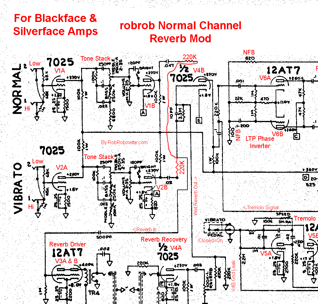
Both channels have a coupling cap and mixing resistor feeding the reverb circuit and the V4B preamp stage. The mixing resistors prevent channel interaction.
Here's the mod, refer to the layout below:
Note: if you're going to do the Lead Channel Mod then do it first because this mod places the Normal channel coupling cap across the cathode resistor and bypass cap.
1. Desolder and pull the Vibrato channel .02uF coupling cap output end loose and bend it upwards. Twist the leads of two 220k 1/2 watt resistors together (new mixing resistors) and solder the twisted end into the empty eyelet. Solder one of the resistors to the coupling cap's free lead.
2. Desolder and pull the Normal channel's .047uF cap's output end and bend it toward the new Normal channel mixing resistor from step 1, solder the .047uF coupling cap to the new Normal channel 220k mixing resistor installed in Step 1.
If you want to change the Normal channel cap's value then simply remove the original cap and solder in the cap of choice as shown in the layout below.
3. The Normal channel original 220k Channel Mix resistor (below at far left) is not in the new circuit so it should be disconnected to prevent the long wire run across the board from becoming an antenna. Leave the Vibrato Channel original 220k Channel Mix resistor in place because it affects the phase inverter's overdrive tone.
robrob Normal Channel Reverb Mod
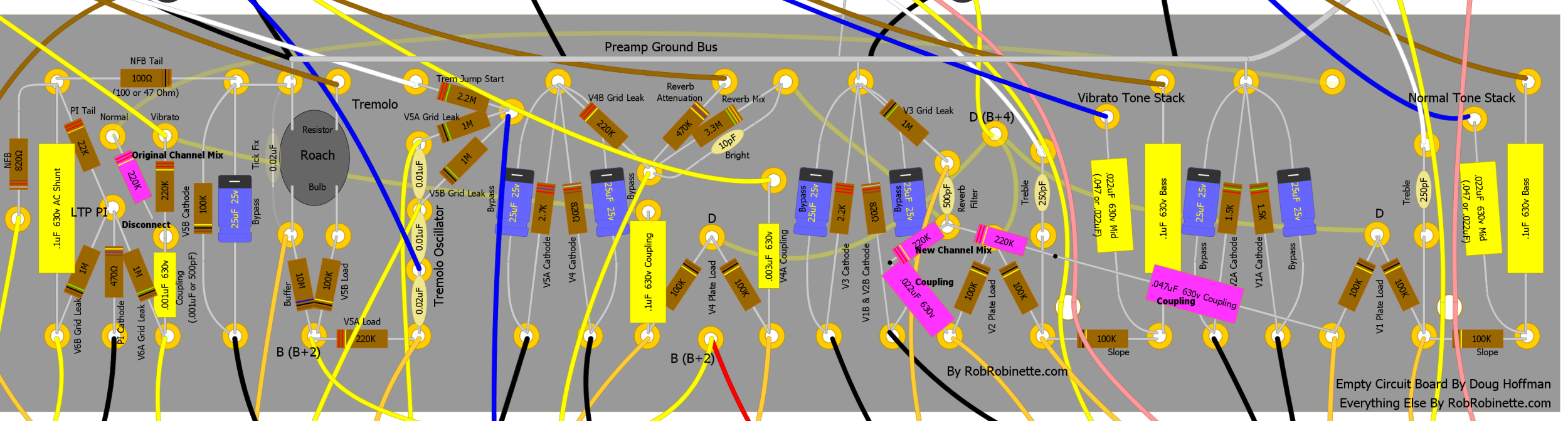
The Normal channel's coupling cap + new 220k Channel Mix resistor easily span the distance to the Vibrato channel's new 220k Channel Mix resistor. Remember to disconnect the original Normal Channel 220k Channel Mix resistor (at far left).
For the 65 DRRI you need to do the following:

The Normal channel 220k mixing resistor is R12 on the circuit board. Its output end (the end connected to R35 and C25) should be carefully unsoldered and lifted.
Solder a jumper wire from the lifted end of R12 and connect it to the input end of the 3.3M Reverb Mix resistor R25 (R25's input end is connected to C12).
For the Vibrato channel a new 220k mixing resistor needs to be inserted: lift the output end of C12 (Vibrato channel coupling cap). The output end is connected to R25.
Connect the lifted end of C12 with its open pad with a 220k 1/2 watt resistor.
Fender Normal Channel Reverb Mod
This simple mod is how Fender added reverb to the 68 Custom Deluxe Reverb's Normal channel. It routes a silverface amp's Normal Channel through the reverb and tremolo effects and through the V4B third preamp gain stage. This mod also puts the two channels in phase so you can jumper the channels together for a slightly thicker tone. This mod removes the Normal Channel's .047uF coupling cap and both channels guitar signal flow through the Vibrato Channel's .022uF coupling cap. This method of running both channels through reverb and tremolo does not use mixing resistors so the two channels affect one another which can cause fluctuating attenuation and distortion. This is why I recommend the method above.
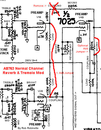
To send the Normal Channel signal through the reverb and tremolo you simply connect the V1B and V2B plates at the bottom (input, nearest tubes) of the two coupling caps. You must also clip or remove the V1B .047uF coupling cap on the right. I recommend just clipping a leg of the cap right at the eyelet so you can easily re-solder it if you ever want to reverse the mod. With this mod I no longer recommend jumpering around the Vibrato channel 220K channel mixing resistor (at far left). Just leave the mixing resistor in place. Click the image to see the full size version. Original photo by John Chabalko.
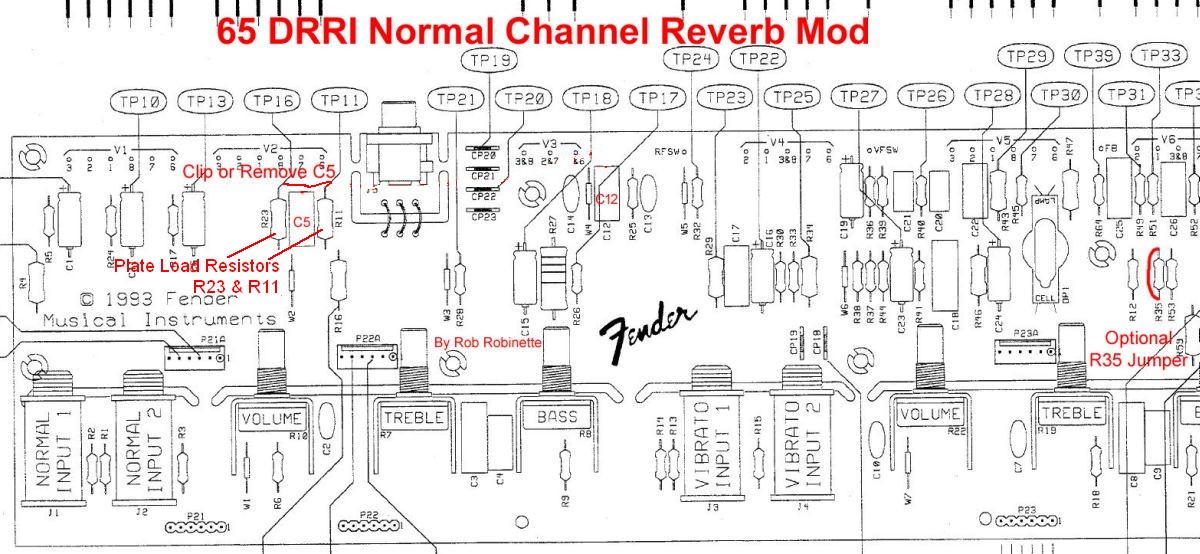
To do this mod to the 65 Deluxe Reverb Reissue you would connect the top of Resistors R23 & R11 with a jumper wire. Clip or remove capacitor C5. I now recommend you leave resistor R35 at far right in place (Vibrato Channel Mixing resistor).
This mod is already done in the 68 Custom Deluxe Reverb.
The "Fritz Mod"
The Fritz Mod is very similar to the above Normal Channel Reverb Mod except that it keeps the Normal Channel coupling capacitor in the circuit. The problem with this mod is the two channels' coupling caps form a capacitive voltage divider and cut the drive from both channels significantly. I recommend the above robrob Reverb Mod above instead. Like the other Normal Channel Reverb Mods above the Fritz Mod also puts the two channels in phase so you can jumper the channels for a fatter tone.
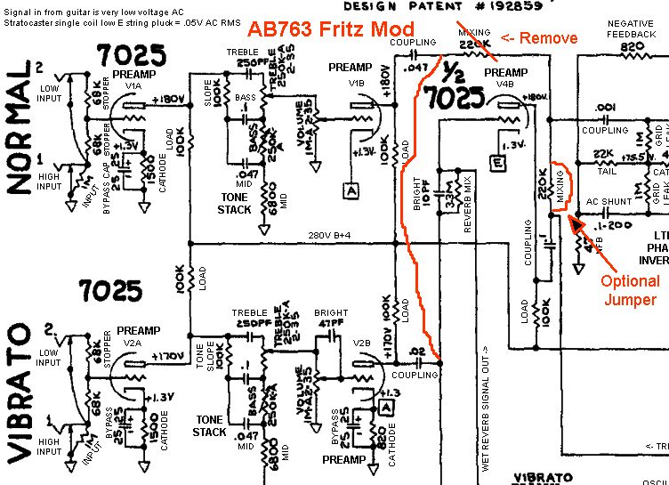
The channels are joined after the coupling caps.
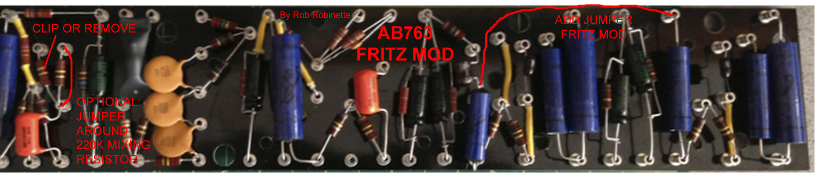
The channel jumper is connected to the output (upper) end of the coupling caps. You must clip or remove the left (Normal Channel) 220k channel mixing resistor at far left above. I now recommend leaving the Vibrato Channel 220k channel mixing resistor at far left in place. Click the image to see the full size version. Original photo by John Chabalko.
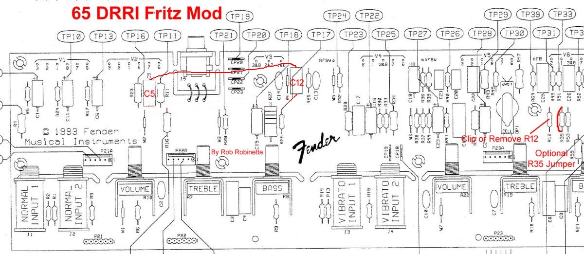
To do the Fritz mod to the 65 Deluxe Reverb Reissue you would connect the output end of capacitor C5 to the output end of capacitor C12. Clip or remove resistor R12 at far right. Leave resistor R35 (Vibrato Channel Mixing resistor next to R12) in place. The circuit board has these parts labeled.
Lead Channel Mod
Many AB763 players never use the Normal Channel since it has lower gain and no effects. If you don't use it you should consider voicing it as a "lead" channel by changing out only four components. Three of these component changes are from the 1987 Marshal "Plexi" lead channel preamp. They filter out excess bass frequencies that tend to boom or get muddy when severely overdriven. You will also gain some clean headroom and maximum volume because low frequencies use up a lot of the amps power so removing very low frequencies allows more amplification of the remaining audio frequencies.
With these four changes you can push the Lead Channel very hard with gain and boost pedals and get a nice, tight, modern overdrive tone. Reverb and delay effects and hot humbucker pickups will also sound better through this "lead" channel because the reduction in low frequencies will keep the amp from being overwhelmed. This mod will also make the channel more pedal friendly in general. I really love the Lead Channel Mod.
When evaluating this mod be sure and try a boost pedal to get the gain and distortion up--this is when this mod really shines.
This mod will not affect the Vibrato Channel. You'll also be able to run more reverb with the Lead Channel because the very low freqs aren't there to freak out the reverb circuit and springs.
Here's an excellent demo showing the difference between the 5E3 unmodified Bright channel and the "Lead Channel:" kdj 5E3 Lead Channel YouTube Demo The difference between the Vibrato and "Lead Channel" won't be quite so stark in the AB763.
The 2.7k cathode resistor is used in many high gain preamps and will bias the preamp cool and make creamy asymmetric distortion more likely. The smaller bypass cap will boost more mids and highs. The .0047uF coupling cap is standard in many modern high gain amps and will trim unneeded low frequencies to tighten up the overdrive tone. This smaller cap will sweeten the overdrive tone by reducing bias drift recovery time of an overdriven second preamp stage. The V1A 220k 1 watt plate load resistor will add gain to the channel's first preamp gain stage and make overdrive more likely in the amp's following gain stages.
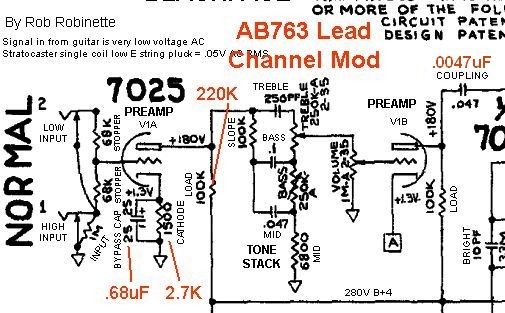
For the mod you increase the V1A cathode resistor from 1.5k to 2.7k (1/2 watt), reduce its bypass cap to .68uF (micro Farad) 25v, increase the plate load resistor from 100k to 220k 1 watt and reduce the big V1B .047uF coupling cap to .0047uF 450V (or higher voltage and yes, that is with two leading zeros).
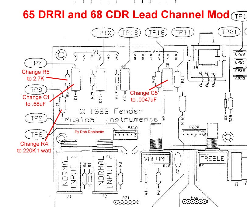
For the 65 Deluxe Reverb Reissue & 68 Custom Deluxe Reverb the V1A cathode resistor is R5. The V1A cathode bypass capacitor is C1. The V1A plate load resistor is R4. The V1B coupling capacitor is C5. On the 68 CDR cap C5 is deleted so don't worry about it. The circuit board has these parts labeled.
Plate Load Resistor Mod
If you would like more gain in the preamp you can swap out one or more of the standard 100k plate load resistors with 220k resistors. A larger plate load resistor will give more signal swing and boost gain. I recommend going with 1 or 2 watt resistors to reduce resistor noise (hiss).
I like to do this to just one channel so consider changing the Normal Channel's V1A and/or V1B plate load resistor. I prefer modifying the Normal Channel first gain stage (V1A) plate load resistor with a 220k 1 watt first. I use this mod in the Lead Channel Mod above.
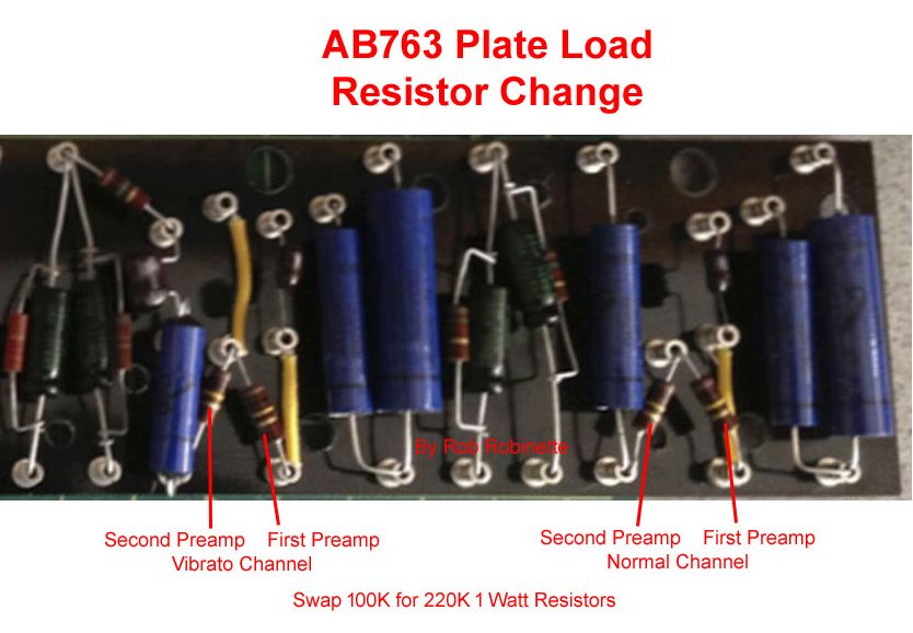
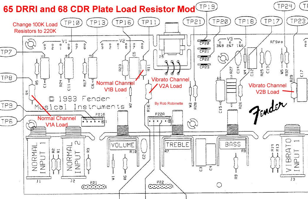
For the 65 Deluxe Reverb Reissue & 68 Custom Deluxe Reverb you would change out V1A Load resistor R4, V1B R11, V2A R16, V2B R29. The circuit board has these parts labeled.
Boost Preamp Voltage
The Deluxe, Deluxe Reverb, Vibrolux and Tremolux amps run with low voltage preamps compared to the other AB763 amps. The schematic for the Deluxe shows only 170 idle volts on the preamp tube plates while the Twin Reverb shows 270v. You can add preamp clean headroom by changing the two power (voltage dropping) resistors to the Twin Reverb values which will bump up the phase inverter and preamp plate voltage. This mod will add preamp headroom and shift the preamp/power amp distortion mix toward the power amp which might actually be too much for the 6V6 power tubes in the Deluxe and Deluxe Reverb. When doing this mod be sure and sample the max volume distortion tone to ensure the power tubes aren't pushed too far. This is an excellent mod for people that want to run 6L6 power tubes in their 6V6 amps. The extra voltage swing will drive the 6L6 harder into distortion and keep the preamp/power amp distortion balance intact.
The high preamp voltage AB763 amps like the Twin Reverb use a 1k 1 watt "C" power node power resistor and 4.7k 1 watt "D" power resistor.
C and D Power Resistors in the Twin Reverb
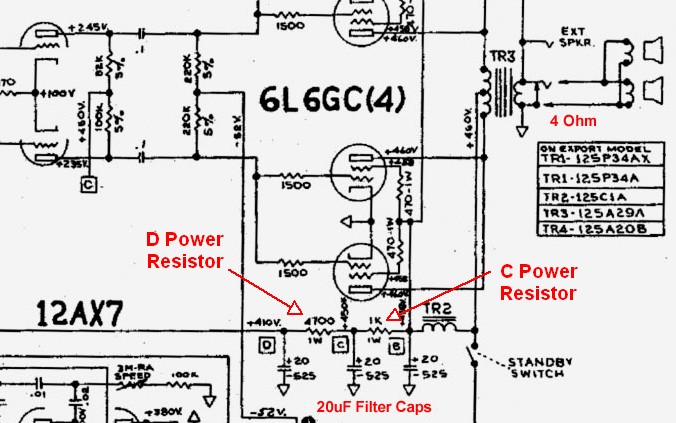
In the Twin Reverb the C Power Resistor is a 1k 1 watt resistor. The D resistor is a 4.7k 1 watt.
I recommend you start by modifying just the C power node power resistor first and sample the modified tone. Reducing the value of the C power resistor will raise the voltage on all the tube plates except the power tubes. Replace the C power resistor with a 1k 3 watt. I recommend a 3 watt rating for these resistors for longevity's sake. The C and D power resistors are located in the "doghouse" which is located outside the chassis next to the output transformer. You can temporarily alligator clip a resistor in parallel with the existing power resistor to try a lower value. For example, the Deluxe Reverb has a 10k C resistor so paralleling a 1.2k (1 watt or higher) will give you 1k of resistance [ 1 / (1/10k + 1/1.2k) = 1k ]
You don't have to use 1k for the C resistor, you can chose any resistor value between the original value and 1k to tweak the tone change to your liking.
If you like the change and want more then replace the D power resistor with a 4.7k 3 watt which will boost only the preamp voltage (and reverb recovery in the reverb amps). Again, you don't have to use a 4.7k resistor here, you can chose any resistor value between the original value and 4.7k.
Deluxe Reverb Power Resistors
The C and D power resistors are located at upper left in the filter cap "doghouse."
Vibrolux & Tremolux Power Resistors
The C and D power resistors are located at upper left in the filter cap "doghouse."
65 DRRI & 68 CDR Power Resistors
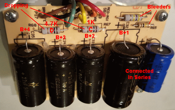
The C and D power (voltage dropping) resistors are located at upper-center left in the filter cap "doghouse."
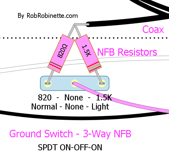
3-Way Negative Feedback Switch
The AB763 uses an 820 ohm negative feedback (NFB) resistor to set the level of feedback. The reissue 68 Custom Deluxe Reverb cuts NFB in half by using a double size 1.5k NFB resistor. The NFB switch fundamentally changes the clean and overdrive tone of the amp. Playability and touch sensitivity are also changed in all three positions. This is a great modification and will really make the amp more versatile.
I like to use the 3-way ON/OFF/ON SPDT Ground Switch to give you: Normal/Light/Heavy negative feedback. You can leave the old 820 ohm NFB resistor in place on the circuit board.
Normal - Light - Heavy 3-Way NFB Switch
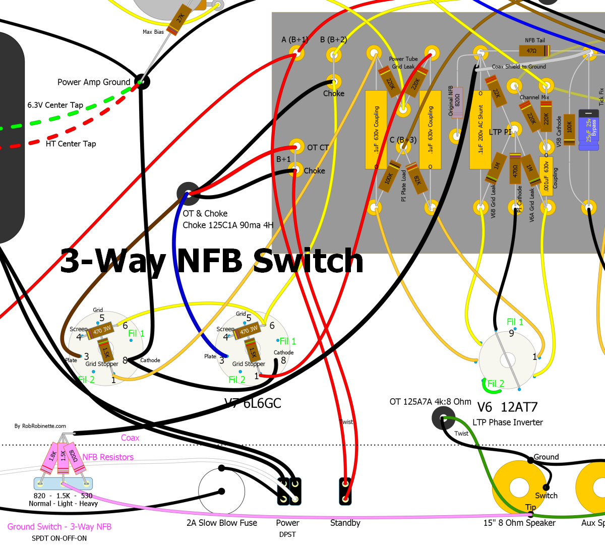
The 3-Way NFB Switch gives you "Normal", "Light" and "Heavy" NFB options. The center position uses only the 1.5k resistor for "Light" NFB (half of normal NFB). The right switch position parallels the 1.8k and 1.5k resistors for factory or "Normal" 820Ω of NFB resistance. The left position parallels the 1.5k and 820Ω resistors for 530Ω of "Heavy" NFB resistance. If you don't want to use the Ground Switch for NFB I suggest installing an SPDT ON/OFF/ON mini switch next to the tremolo intensity pot or on the back panel.
Another Switch Configuration
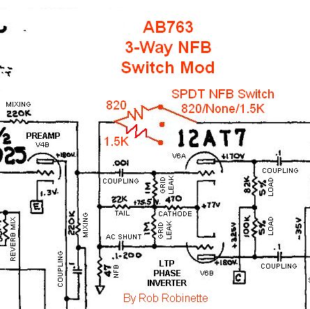
If you want a "No NFB" switch position then wire the switch like this. With the switch to the right you get Normal NFB with an 820 ohm resistor. Switch in the middle positions disconnects NFB. In the left position we get the 68 CDR "Light" NFB with a 1.5k resistor.
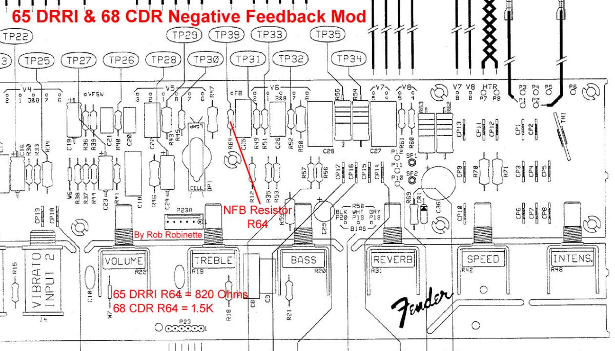
For the 65 Deluxe Reverb Reissue & 68 Custom Deluxe Reverb the negative feedback resistor is R64. It is 820 ohms for the '65 and 1.5k for the '68. The circuit board has this part labeled.
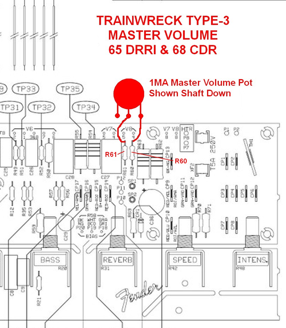
Master Volume Mod
There are many master volume options but the Trainwreck Type-3 Post Phase Inverter Master Volume (PPIMV) is very easy to install and it works almost as well as any other master volume I've tried in any of my amps. This master volume controls the signal level feeding the power tubes so you can use it for lower volume distortion and to control the balance between preamp and power tube distortion. It works by mixing the two phase inverter output streams together and they cancel each other out. Less resistance = more signal mix and less output volume.
For the Type-3 master volume you simply add a 1 mega ohm audio (log) pot and two wires. It's easy to temporarily alligator clip the pot into the circuit to give it a try. When the Master Volume pot is set to max the master volume circuit virtually disappears and will not color the amp's tone.
You can place your master volume pot anywhere but you may have to use shielded wire to prevent noise or oscillation. I use RG-174 coax cable when I need shielded coax in an amp. Only ground one end of any coax cable in an amp, preferably the signal input end, to keep from forming a ground loop. Shielded microphone cable with 4 conductors can also be used so you would have only one cable which makes for a cleaner install. If you keep the wire runs relatively short and away from the power transformer end of the amp you should be OK without using shielded coax.
Simple But Effective Trainwreck Type-3 Post Phase Inverter Master Volume (PPIMV)
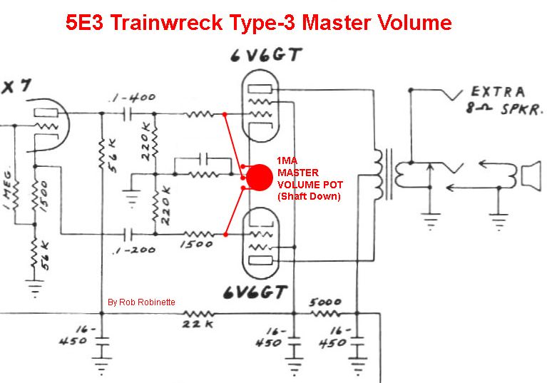
Add a 1 megaohm audio (log) pot and two wires and you've got an effective post phase inverter Master Volume. As you turn the Master Volume pot down (counterclockwise, pot is shown shaft down) more of the opposite phase signals from the phase inverter are mixed together which cancels the signal out. I highly recommend using RG174 shielded coax to make the runs to the pot to minimize noise. I did this mod to my 5F6A Bassman and it works great.
Trainwreck Type-3 Post Phase Inverter Master Volume (PPIMV)

Add a 1 megaohm audio (log) pot and two wires and you've got an effective post phase inverter Master Volume. As you turn the Master Volume pot down (counterclockwise) more of the opposite phase signals from the phase inverter are mixed together which cancels the signal out. The pot is shown shaft down in the layout. Ground the RG174 coax shield only at one end.
If you are anal you can completely eliminate the Type-3 from the amp circuit by adding a switch to disconnect the circuit. Use a 250KA pot with a push-pull DPDT switch and wire one leg of the master volume through the switch so when the master volume knob is down the circuit is completely disconnected. Pull the knob up to activate the master volume. A 250KA pot will give you a better volume sweep than a 1MA and since we can disconnect the MV we don't have to worry about the 250KA pot affecting the amp tone.
To do this you would run the wire from the #2 (center) pot terminal to the upper left DPDT switch terminal, then run a wire from the middle left DPDT switch terminal to the circuit board's right 220k resistor. The wire from the #1 (left) pot terminal would be wired as normal to the left 220k resistor (see layout below).
Type-3 With MV ON/OFF Push-Pull Pot
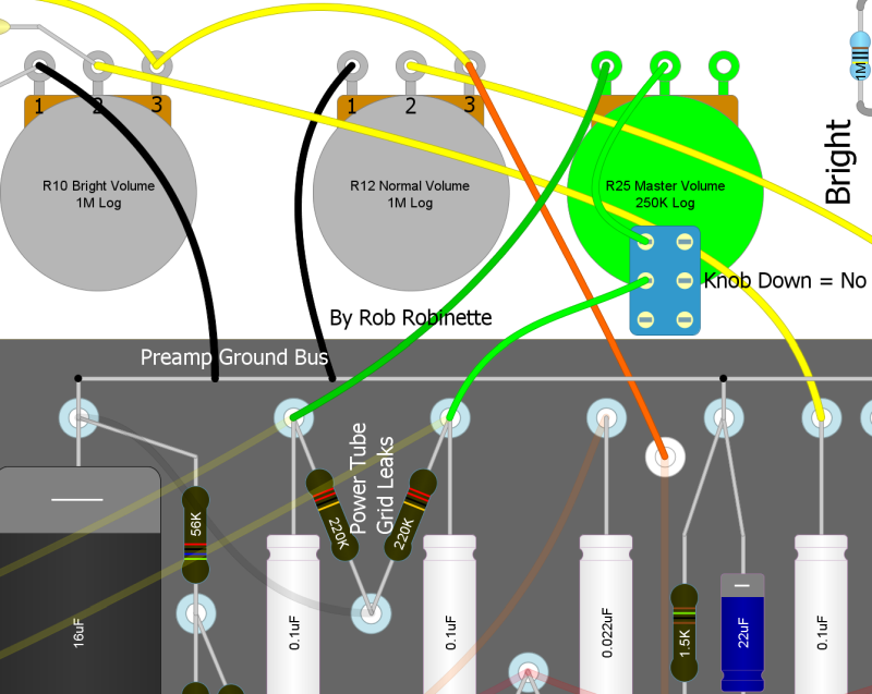
Master Volume knob Down = no master volume at all, Up = master volume on. This diagram shows a 5E3 Deluxe but the push-pull switch wiring is the same.
Another option is to use a switch and resistor for your master volume instead of a pot. You simply replace the master volume pot with a resistor on a switch. One guy used a 5k 1/2 watt resistor which gave him his preferred "bedroom practice" output level. Switch OFF = no master volume at all, ON = bedroom volume.
Trainwreck Type-2/Lar-Mar Master Volume
If you are building an AB763 amp then I recommend installing the Trainwreck Type-2 or Lar-Mar master volume. It is more "transparent" and virtually disappears when at max master volume setting. It is much more difficult to add to an existing amp so for modding an existing amp I recommend the Type-3 master volume.
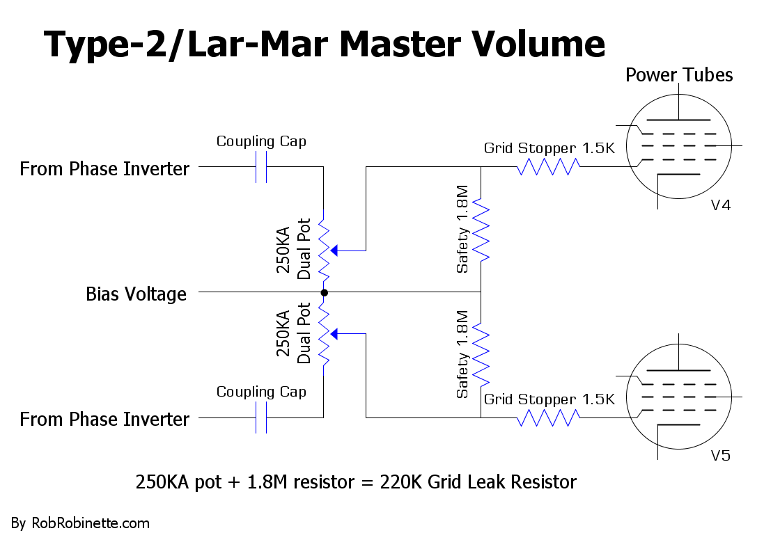
When the master volume is turned down the guitar signal is bled to ground through the bias circuit. The 1.8M Safety resistors allow bias voltage to pass around the master volume pot in case of a wiper failure. The resistors also lower the max grid leak resistance to 220k to match the stock grid leak resistors.
Trainwreck Type-2/Lar-Mar Master Volume
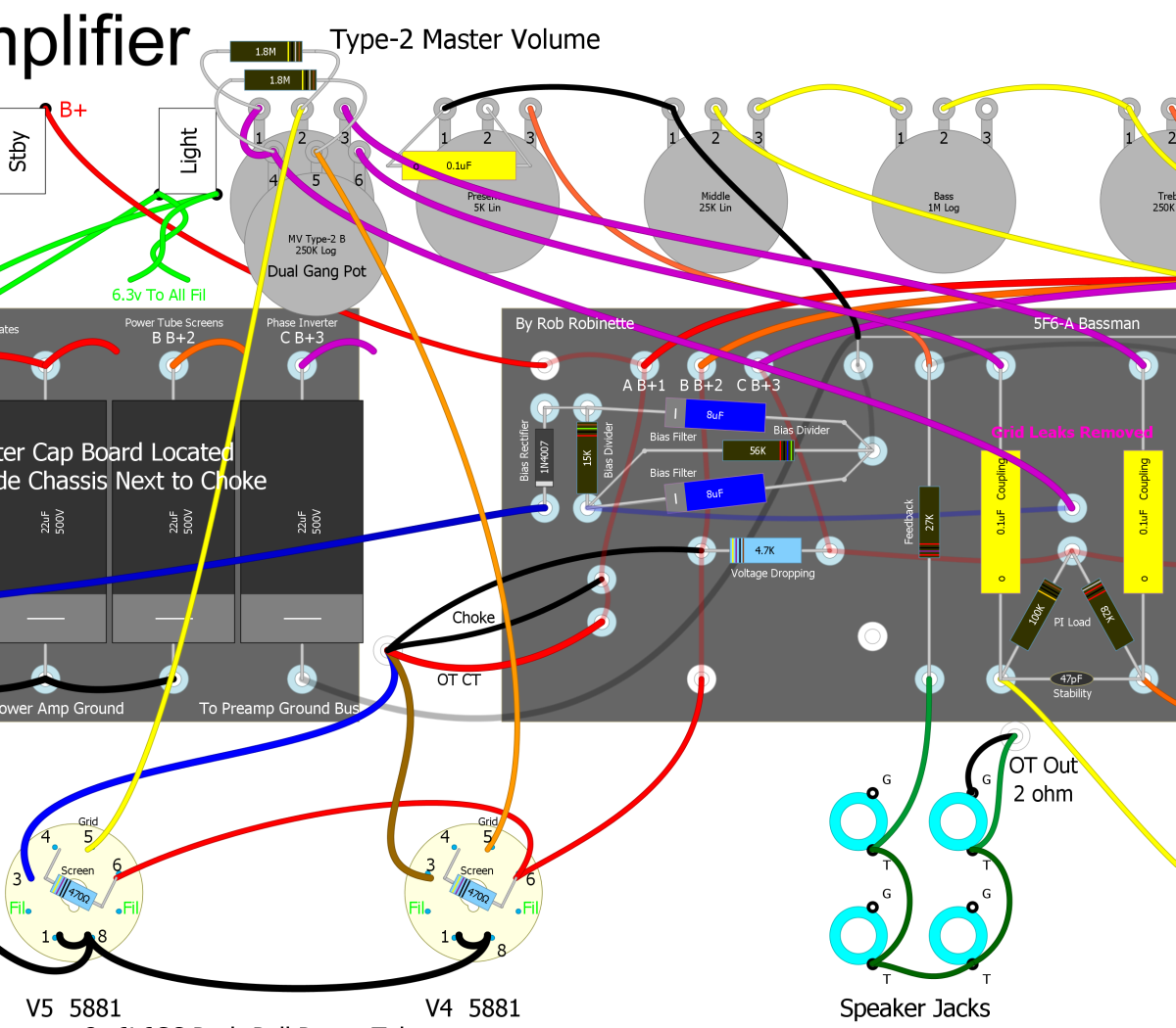
Type-2/Lar-Mar master volume shown on a 5F6A Bassman but the implementation is the same in AB763 amps. A dual gang 250KA pot (one shaft turns both pots, audio or log taper) replaces the two 220k power tube grid leak resistors. This is the most transparent of all the master volume types. The 1.8M resistors on the Master Volume pot reduce the pot resistance to 220k (the stock value) and add a failsafe path for bias voltage.
Vox Cut Control & Cut Control + Master Volume
I'm a big fan of the VOX style Cut Control because it's a great way to "trim the ice pick". Early in-the-circuit tone controls affect the substance of the overdrive tone. High freqs generate overdrive harmonics that fill in the top end. If you turn down a normal tone control to reduce ice-pick highs you'll kill all the harmonics too. A cut control allows you to trim off very high ice pick highs without removing all the high frequency overdrive harmonics. All high gain amps should have early and late tone controls for this reason. You can just leave the cut control on full high and you have a normal amp circuit.
The Vox Cut Control connects the two power tube grids with a 220k audio pot and 4.7nF (.0047uF) capacitor to allow variable high end cut. In a push-pull amp the guitar audio signals on the two power tube grids are 180 degrees out of phase with one another so mixing them together nullifies the signal, kind of like mixing matter and antimatter. The capacitor limits the effect to high frequencies but if you jumper around the cap the pot becomes a Trainwreck Type-3 Master Volume.
I like this very late tone tweak because it pairs well with an early tone control or stack. Use the early tone control to get the overdrive tone and substance you want then use the Cut Control to fine tune the tone. The Cut Control affects only the power tubes.
Wire the cut pot as a variable resistor so that as you turn the knob up (clockwise) resistance increases. Up = more resistance = brighter tone.
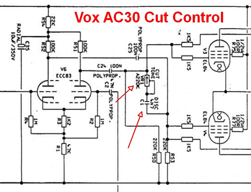
220KA or 250KA pot (audio pot wired as variable resistor) and .0047uF 200v cap connect the two phase inverter outputs.
Cut Control on 5F6A Bassman
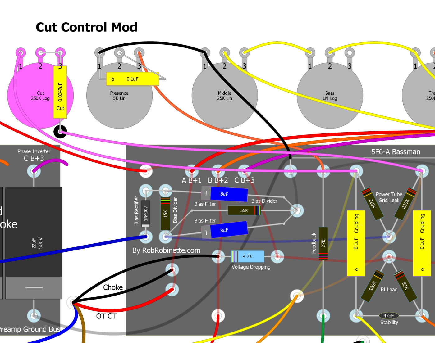
The Cut Control is shown on a 5F6A but the mod is identical on an AB763. The .0047uF Cut Cap can be supported by a non-grounded terminal strip.
Master Volume + Cut Control Push-Pull Pot Mod
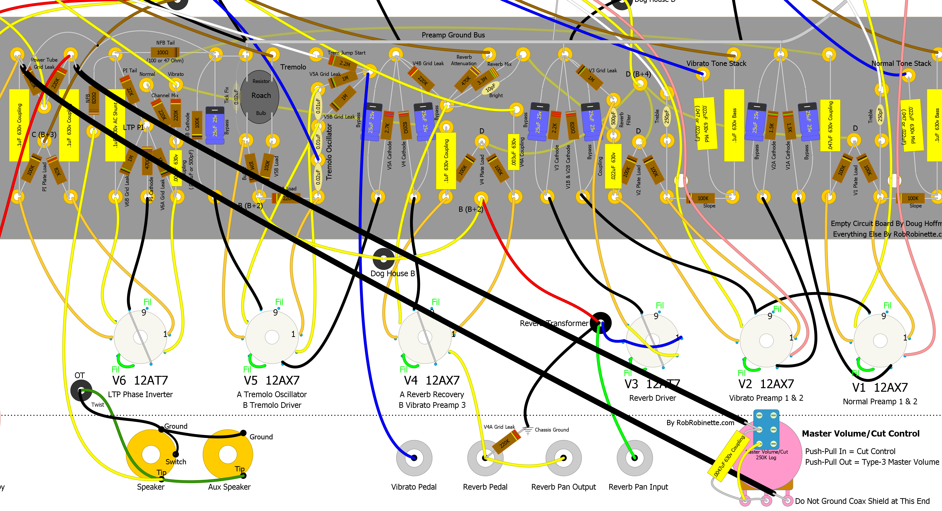
You can turn a Cut Control into a Trainwreck Type-3 Master Volume by simply jumpering around the Cut Cap. Use a 250KA push-pull pot and you can push the pot down for Cut Control or pull it up for Master Volume. Connect the "cut capacitor" from pot terminal #3 to the middle switch terminal.
1/4 Power Switch
This very cool 1/4 Power Switch is from the 20 watt Fender Eric Clapton Tremolux. The switch cuts the amp's output power by 75%, down to about 5 watts. The switch places an 8 ohm 25 watt resistor in series with the 8 ohm amplifier speaker (for a total of 16 ohms and a 50% cut in power), then places a 16 ohm 25 watt resistor in parallel to bring the total speaker load back down to 8 ohms and gives another 50% cut in power. The two resistors turn 3/4 of the amp's output signal into heat. With the switch in the "Normal" position the 8 ohm resistor is bypassed and the 16 ohm resistor is disconnected.
The Eric Clapton Tremolux is a 2x6V6 fixed bias amp putting out about 20 watts so this circuit will work with any amp with similar or lower output.
You can use the 1/4 Power Switch with the internal speaker and an external cab simultaneously but the speakers' load will drop to 4 ohms so most of the power will bypass the 16 ohm resistor and flow through the 8 ohm resistor and speakers. Total load on the output transformer drops to 6.8 ohms but the Fender 8 ohm transformer is designed to work with two parallel speakers at a 4 ohm load so it's not a problem.
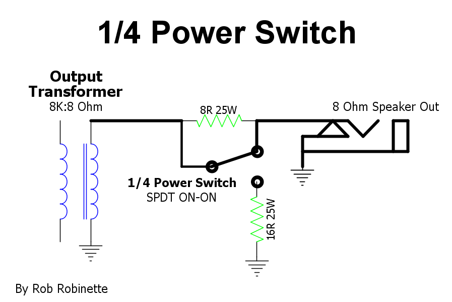
The 8 ohm 25w resistor is placed in series with the amplifier speaker and the 16 ohm 25 watt resistor is placed in parallel to bring the total speaker load back down to 8 ohms. If your amp does not have an Aux speaker jack just connect the 16 ohm resistor and switch wire to the speaker jack's Tip and Ground terminals.
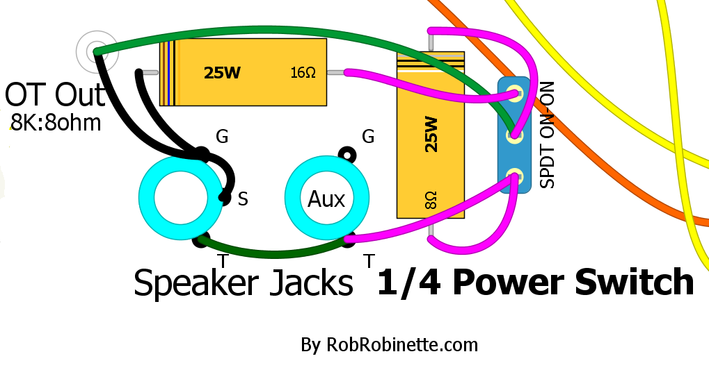
T=Tip and G=Ground.
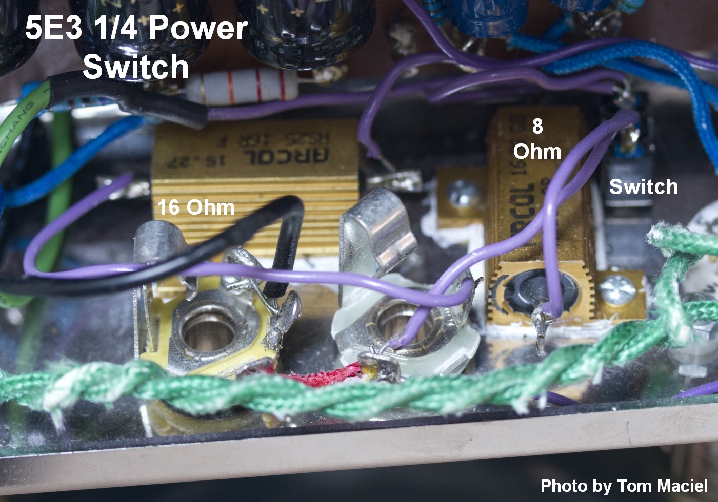
Large, gold colored 25 watt chassis mount resistors with 1/4 Power Switch at upper right. Photo by Tom Maciel.
Mouser.com: 8 ohm 25 watt wire wound chassis mount resistor, 16 ohm 25 watt resistor. The resistors are about $3 each.
These are chassis mount resistors and should be screwed or bolted to the chassis to dissipate heat. If they are not bolted to the chassis their heat rating drops to about 5 watts.
For a 4 ohm output transformer secondary change the resistors to a 4 ohm 25 watt and 8 ohm 25 watt.
For a 16 ohm output transformer secondary change the resistors to a 16 ohm 25 watt and 32 ohm 25 watt.
For a 1x6V6 cathode biased amp like the 5F1 Champ 10 watt chassis mounted resistors would be fine.
10% Power Switch
Several builders have complained that the 1/4 Power Switch shown above, which cuts 75% of the output power, only sounds like a 30 to 50% volume cut due to how our ears perceive volume. If you really want near-bedroom volume levels then a 90% cut in power can be attained by using a 16 ohm 25W resistor for the upper resistor and a 12 ohm 25W resistor for the lower resistor (8 ohm output transformer secondary). The 12 ohm resistor will burn most of the amp's output so for anything more powerful than a cathode biased push-pull 6V6 amp like the 5E3 Deluxe you'll need to bump the 12 ohm resistor's power handling to 50 watts to be safe (two 25 ohm 25 watt resistors in parallel will work).
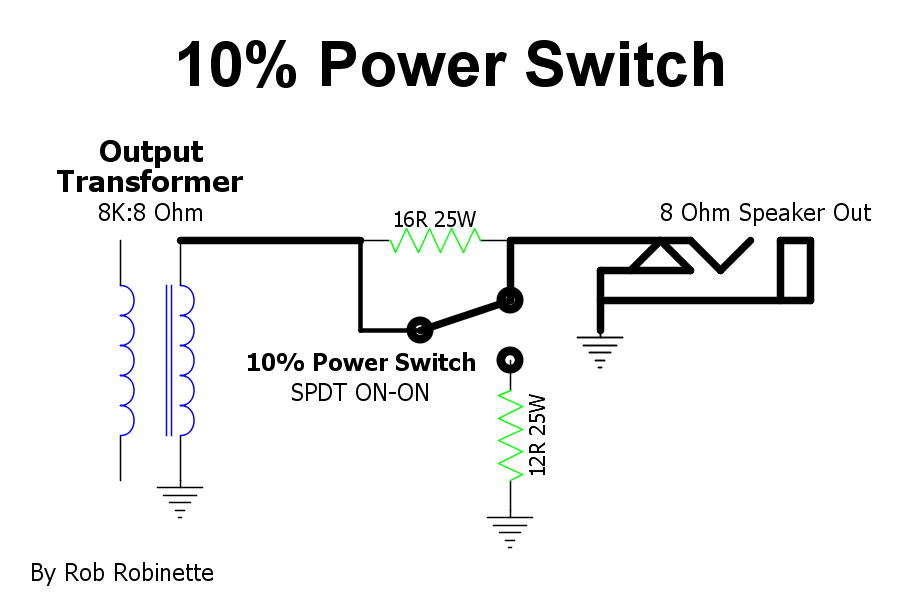
90% of the amp's output power will be converted to heat.
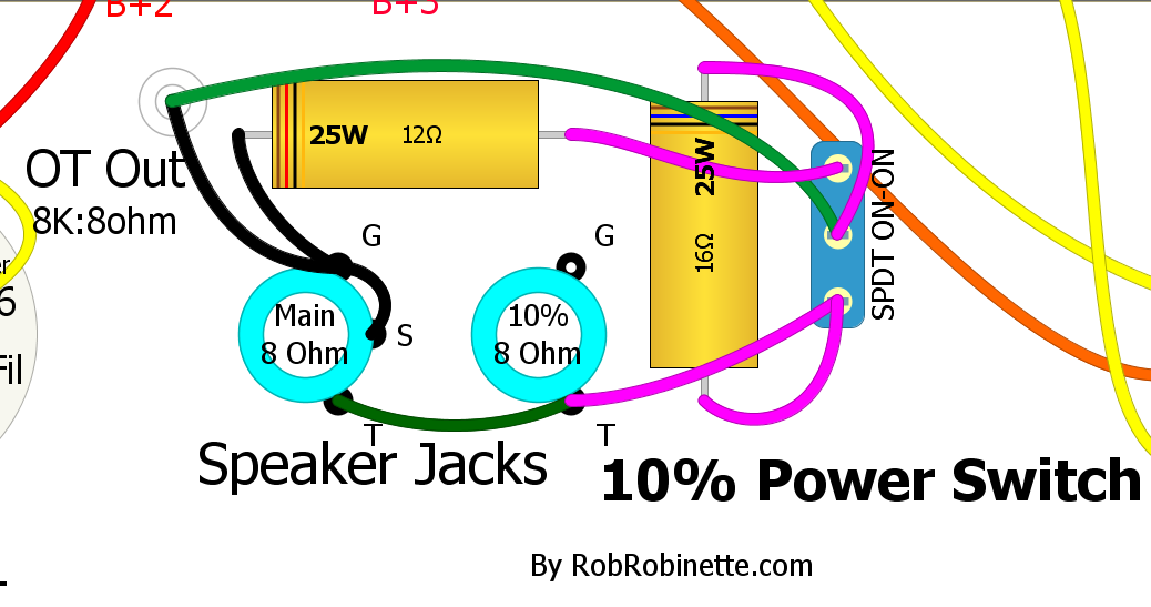
With the switch set to 10% both jacks will be 8 ohm with 90% of the amp power turned into resistor heat. These 25 watt resistors are adequate for 15 watt amps such as a 5E3 Deluxe or other cathode biased 6V6 push-pull amps.
These are chassis mount resistors and should be screwed or bolted to the chassis to dissipate heat. If they are not bolted to the chassis their heat rating drops to about 5 watts.
For 25 watt amps such as a blackface or silver face Deluxe or other fixed bias 2x6V6 push-pull amps I recommend 50 watt resistors (two 25 watt resistors in parallel will also give you 50 watts).
For 50 watt amps such as 2x6L6 amps I recommend 100 watt resistors (two 50 watt resistors in parallel will also give you 100 watts).
For a 100 watt amp such as 4x6L6 amps I recommend 200 watt resistors (two 100 watt resistors in parallel will also give you 200 watts). These would be difficult to stuff into an amp chassis.
For a 2 ohm output transformer secondary you would use 3 and 4 ohm resistors.
For a 4 ohm output transformer secondary you would use 6 and 8 ohm resistors.
For a 16 ohm output transformer secondary you would use 24 and 32 ohm resistors.
If your amp has a negative feedback loop then tap it from the main speaker jack tip connection.
10% Power Jack
You can wire your speaker aux jack as a 10% power output jack. This mod uses the circuit above but uses the main speaker jack switch to switch between full power and 10%.
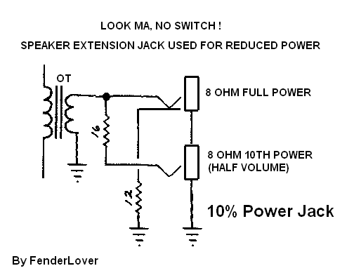
The main speaker jack on the left is 8 ohm full power. The 10% jack on the right is 8 ohm but 90% of the amp output power is burned in the two 25 watt resistors. These 25 watt resistors are adequate for 15 watt amps such as a 5E3 Deluxe or other cathode biased 6V6 push-pull amps.
These are chassis mount resistors and should be screwed or bolted to the chassis to dissipate heat. If they are not bolted to the chassis their heat rating drops to about 5 watts.
For 25 watt amps such as a blackface or silver face Deluxe or other fixed bias 2x6V6 push-pull amps I recommend 50 watt resistors (two 25 watt resistors in parallel will give you 50 watts).
For 50 watt amps such as 2x6L6 amps I recommend 100 watt resistors (two 50 watt resistors in parallel will also give you 100 watts).
For a 100 watt amp such as 4x6L6 amps I recommend 200 watt resistors (two 100 watt resistors in parallel will also give you 200 watts). These would be difficult to stuff into an amp chassis.
For a 2 ohm output transformer secondary you would use 3 and 4 ohm resistors.
For a 4 ohm output transformer secondary you would use 6 and 8 ohm resistors.
For a 16 ohm output transformer secondary you would use 24 and 32 ohm resistors.
If your amp has a negative feedback loop then tap it from the main speaker jack tip connection.
10% Power In External Box
This is the 10% power circuit in a box. The amp speaker out plugs into the IN jack and the speaker is plugged into the OUT jack.
These are chassis mount resistors and should be screwed or bolted to the box to dissipate heat. If they are not bolted to the chassis their heat rating drops to about 5 watts.
For 25 watt amps such as a blackface or silver face Deluxe or other fixed bias 2x6V6 push-pull amps I recommend 50 watt resistors (two 25 watt resistors in parallel will also give you 50 watts).
For 50 watt amps such as 2x6L6 amps I recommend 100 watt resistors (two 50 watt resistors in parallel will also give you 100 watts).
For a 100 watt amp such as 4x6L6 amps I recommend 200 watt resistors (two 100 watt resistors in parallel will also give you 200 watts). I don't recommend this because the box would have to be really big to provide an adequate heat sink for the big resistors.
For a 2 ohm output transformer secondary you would use 3 and 4 ohm resistors.
For a 4 ohm output transformer secondary you would use 6 and 8 ohm resistors.
For a 16 ohm output transformer secondary you would use 24 and 32 ohm resistors.
1/2 Power Switch
This is a standard 'Pentode / Triode' type switch that lowers the power tube output for lower maximum volume. In reality this switch changes the 6V6 power tube from a pentode (5 electrodes: cathode, control grid, plate, screen grid and suppressor grid) to a tetrode (4 electrodes since the screen grid is deactivated) but by convention we call it a pentode / triode switch.
A triode tube's plate normally 'pulls' free electrons from the cathode but a triode's plate voltage fluctuates as it amplifies a guitar audio signal. When the plate voltage drops it does not pull electrons as hard as it does when the plate voltage is high. Adding a fixed, high voltage screen grid makes a tube much more efficient because the screen's constant strong pull of electrons does not drop when the plate's voltage drops so the tube flows more electrons.
The Half Power Switch (ON-ON DPDT mini switch) connects the power tube screens (pin 4) to B+2 (normal full power pentode) or to the power tube plates (pin 3 for half power 'triode' mode). Removing B+2 and tying the power tubes' screen and plate together deactivates the screen by allowing the screen voltage to fluctuate along with the plate voltage effectively creating a lower power 'triode.' Running a pentode in 'triode' mode definitely changes its clean and overdrive tone so it's more than just a 'half power' mode.
Half Power Switch in the BootHillAmps.com SixShooter
Power tube screen grid is connected to either the plate in the triode mode, or the B+2 screen power supply in the pentode mode.
This is a simple mod because there's room between the power tubes for the mini switch so the resistors can be connected directly between the tube sockets and switch. 470Ω 2 watt screen resistors are added to keep the screen voltage slightly lower than plate voltage. These resistors have no effect on amp tone but give the added benefit of protecting the power tubes from excessive screen current which can extend the life of your power tubes.
With the switch lever 'IN' you get normal full power. With the lever 'OUT' you get 'tetrode' half power.
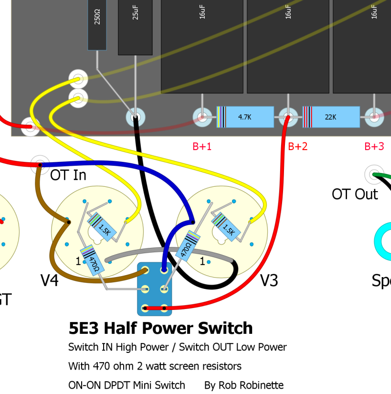
This is my recommended layout with 470Ω 2 watt screen resistors always in circuit to provide excess screen current protection.
Alternate Design With Screen Resistors Used only For Low Power
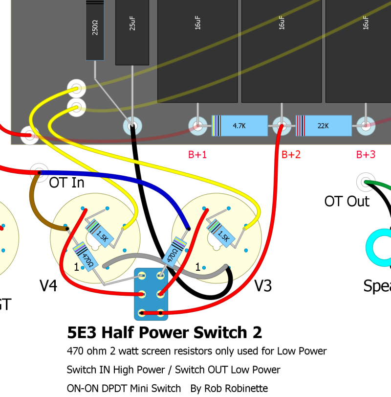
470Ω Screen Resistors moved to switch input so they are only used in the 'Low Power' switch position. Use this layout if you don't want to alter your 5E3's circuit with the switch in the normal 'High Power' position.
Add a Presence Control
I'm a fan of late-in-the-circuit tone controls which allow tone tweaks with less side effects and the Presence Control is one of my favorites. It's actually pretty easy to add a Presence Control to any blackface or silverface amp with a long tail pair phase inverter.
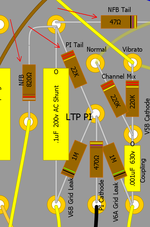
To add the Presence Control we'll delete the NFB Tail resistor and replace it with a 25KL pot with a .1uF (600v poly) cap and 4.7k 1/2 watt resistor. We also have to adjust the size of the NFB resistor and the phase inverter tail resistor (PI Tail in layout) to compensate for the presence control's added resistance (going from 47 ohm NFB tail to 4.7k of tail resistance). With this presence circuit you'll get standard AB763 tone with the presence pot turned full down.
The 4.7k presence resistor on the presence pot acts as the NFB Tail resistor. The .1uF cap blocks DC flow through the pot to eliminate "static" when adjusting the control. The cap also sends high frequencies from the NFB loop to ground which boosts highs at the speaker. These boosted highs have less NFB so they are "thicker and harrier" with additional harmonic and intermodulation distortion which adds "presence". Since the back of the presence pot is used as a ground be sure and use a star washer on the pot to ensure good pot-to-chassis contact.
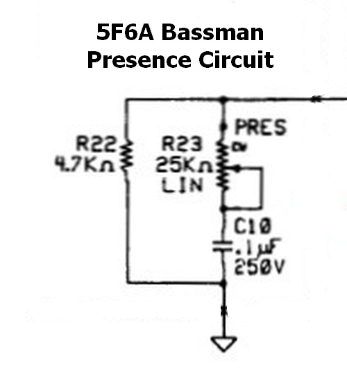
The Presence Cap bleeds NFB high frequencies to ground and also blocks DC from flowing through the Presence pot. This circuit differs from the Fender 5F6A schematic and layout but matches what was actually installed in most 5F6As from the factory.
The NFB Resistor and NFB Tail resistor form a voltage divider to set the NFB signal level. The ratio of this voltage divider can be used to calculate the value of our new NFB Resistor. Blackface amps use an 820 ohm NFB resistor with either a 47 or 100 ohm NFB Tail resistor. The 47 ohm NFB tail resistor was used in amps with 8 ohm outputs and the 100 ohm resistor was used to compensate for the lower voltage put out by 4 and 2 ohm power transformer secondaries.
Blackface/Silverface NFB Circuit
The ratio of our silverface amps with a 47 ohm NFB Tail resistor is 820 / 47 = 17.4. Since the NFB tail resistance is being increased from 47 to 4.7k we can use this NFB ratio to calculate the appropriate NFB resistor to pair with the presence circuit: 4.7k * 17.4 = 82k for the new NFB resistor.
For amps with a 100 ohm NFB Tail resistor we use 820 / 100 = 8.2, 4.7k * 8.2 = 38.5k. The nearest standard resistor value is a 39k NFB resistor for amps with 100 ohm NFB Tail resistors.
Since the Presence control adds 4.7k of tail resistance to the phase inverter circuit we need to decrease the PI Tail resistor from 22k to 18k to compensate.
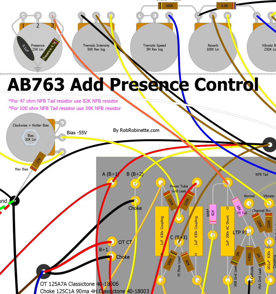
To add a Presence Control we delete the NFB Tail resistor from the circuit board (47 or 100 ohm) and replace it with a 4.7k Presence resistor mounted on the Presence pot. The .1uF Presence capacitor forms an RC low pass filter with the NFB resistor. The Presence pot is wired as a variable resistor to control how much high frequency signal is bled through the cap to ground. The NFB resistor is increased to 82k and the PI Tail resistor is reduced by 4k to make up for the added NFB tail resistance. The NFB resistor should be 82k for amps with a 47 ohm NFB Tail resistor and 39k for amps with a 100 ohm NFB Tail.
Turn Presence Control Into Variable NFB
By simply adding a large parallel capacitor to a presence control we can turn the presence control into a variable negative feedback control. The typical presence control capacitor is .1uF and is used to bleed high frequencies from the NFB circuit. Removing high frequencies from the NFB boosts high frequencies at the speaker. By adding a switched large parallel 10uF or larger (250v or higher) capacitor we can send all frequencies to ground and create variable NFB. I recommend putting the 10uF parallel cap on a switch so you can switch from presence to NFB control.
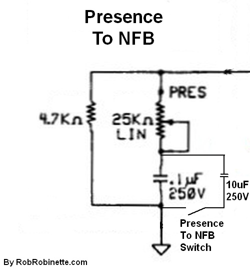
Added switched parallel 10uF (or larger) 250v (or higher) capacitor. The switch is a SPST (single post single throw) with open = Presence, closed = NFB Conrol.
I recommend using shielded cable such as RG174 or for a very clean install use a shielded multi-conductor microphone cable and use one conductor to the switch and another conductor from the switch. Ground the cable shield at one end only, whichever end has the easiest access to a ground which is probably the back of the presence pot.
Add a Mid Tone Pot
In the standard Fender tone stack a 6.8k Mid resistor is used in amps without a Mid pot (usually a 10KA pot). You can simply replace that 6.8k resistor with a pot wired as a variable resistor. A 10KA Mid pot is Fender standard but a 25KA, 50KA or 100KA can be used to give the Mid tone control more authority. Turning a 100KA Mid pot up adds resistance to the tone stack ground which "removes" the entire tone stack for a flatter tone curve and less signal load so you also get more gain. Turning the 100KA Mid pot up high gives us a "tweed" type tone due to a flatter tone curve and more gain. Also, as you turn up the Mid control the bass and treble pots will have less effect.
My personal favorite Mid tone control is a 6.8k resistor in series with a 100KA Mid pot. This allows me to set the Mid control to minimum and get Fender "normal" 6.8k mid resistance. Turn it up and I transition from blackface to tweed tone.
The AB763 Tone Stack
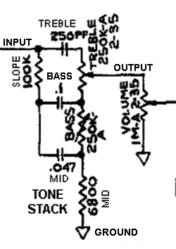
The 6.8k Mid resistor is at the bottom of the schematic. It serves as the entire tone stack's ground connection. Adding Mid resistance adds mid frequencies and reduces the tone stack load which adds gain. Disconnecting the Mid resistor will completely remove the tone stack from the amp circuit.
AB763 Amp With a 6.8k Mid Resistor and No Mid Pot
The 6.8k Mid resistor supplies the tone stack connection to ground. The bottom of the resistor is connected to the preamp ground bus bar.
AB763 Amp With a Mid Pot
The Mid pot simply replaces the 6.8k Mid resistor.
My Favorite Mid Control Setup
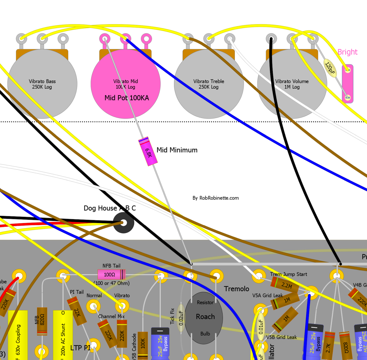
100KA Mid/Raw pot with a 6.8k Mid Minimum resistor allows rolling the pot down to minimum to get "normal" Fender 6.8k mid tone. Turn up the pot a little to add mids, turn it up a lot and you approach tweed tone with flat tone curve and more preamp gain. You can also use a 25KA or 50KA Mid pot for less max tweed. Note that if a Presence pot ground is connected to the Mid pot you will need to run the presence pot directly to ground--do not run its ground through the 6.8k Mid Minimum resistor.
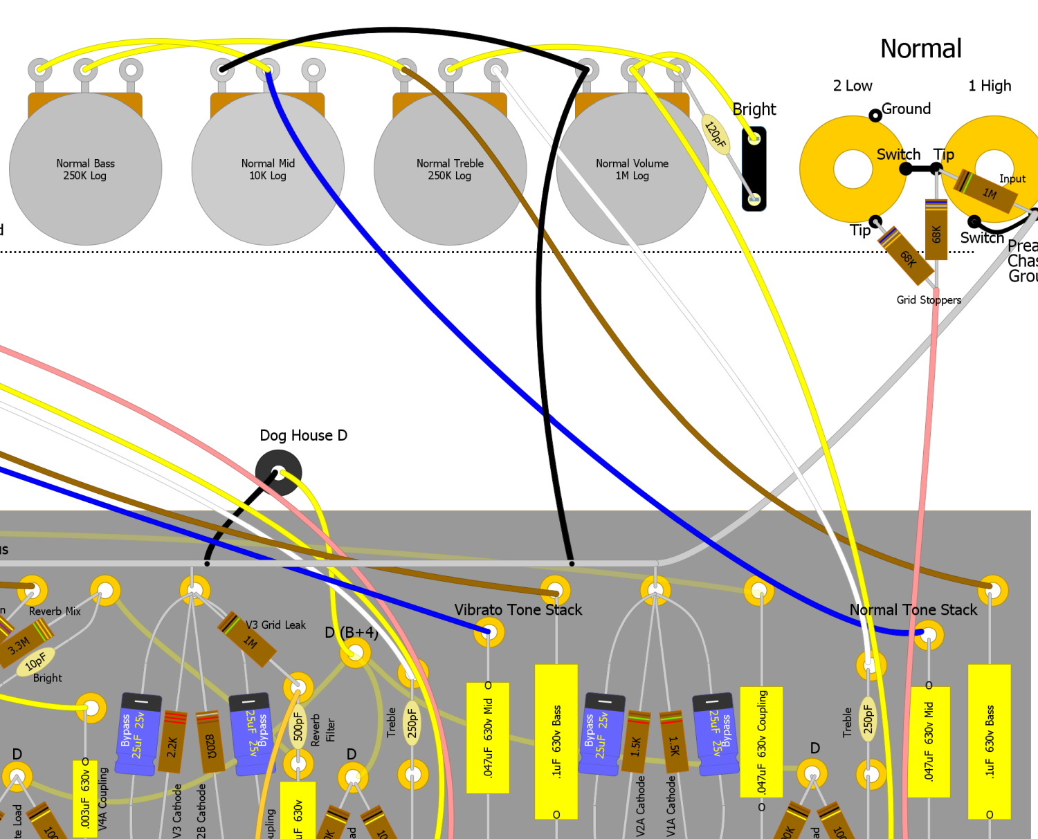
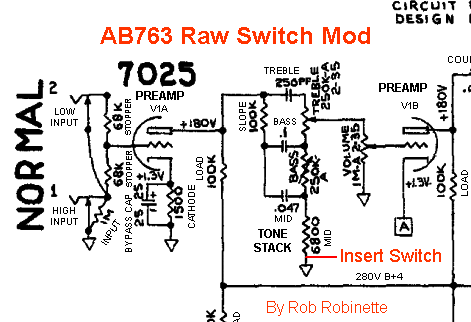
Raw Switch Mod
This is a great mod for pretty much any amp with a TMB (treble mid bass) tone stack. Because this type of tone stack really loads down the guitar signal being able to eliminate the tone stack is a valuable option. Just add an SPST ON/OFF mini-switch to the 6.8k Middle tone resistor's ground. No ground = no tone stack which gives you a very significant signal boost and pure "raw" unaltered tone. The raw tone has a non-scooped mid similar to the no-tone-stack tweed amps such as the 5E3 Deluxe. It also works great with EQ pedals because it lets the pedal do all the tone shaping.
If you feel the jump in gain is too much or the raw tone is too wooly you can reduce the raw boost effect by putting a resistor between the two raw switch terminals so when the switch opens for "raw tone" some tone stack current can still flow. Opening the raw switch will add the resistor value to the tone stack mid cap value. When the raw switch is in the normal, closed position the raw switch resistor is bypassed.
Raw Switch On and Off
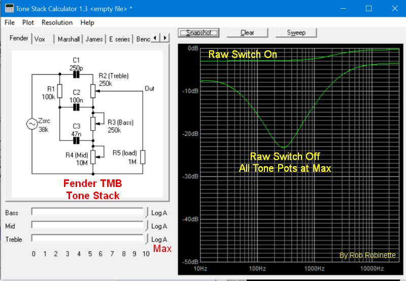
You can see how even with all three tone pots at max what a huge boost in signal you get when the Raw Switch is engaged (tone stack ground disconnected). The mid scoop is also flattened out. Chart is from the Duncan Tone Stack Calculator.
I placed my Raw mini-switch between the Treble and Bass pots.
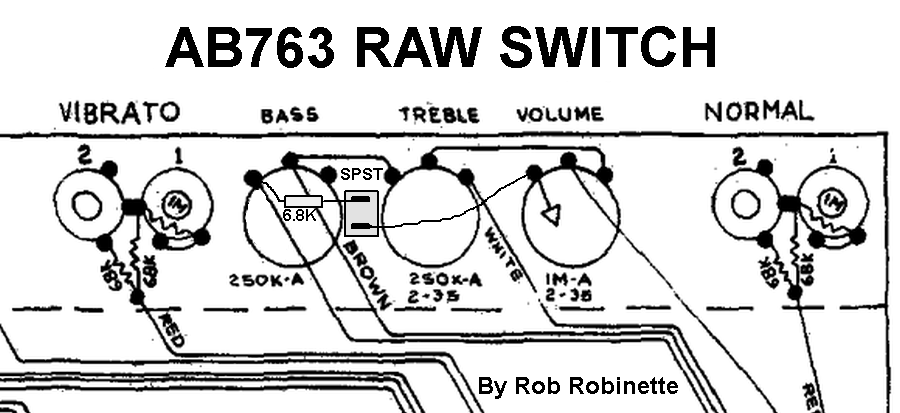
Raw switch added to AB763 Normal Channel. The switch is grounded at the Volume pot ground. The switch is a SPST (Single Post, Single Throw) ON/OFF mini-switch.
The 6.8k Mid resistors are located on both Bass pots. Just remove the resistor from the pot and connect the pot's left terminal to a Raw switch terminal with a new 6.8k 1/2 watt resistor (the leads of the original resistor won't be long enough to reach the switch). Connect the other switch terminal to ground and you're done.
With the switch in the connected position the tone stack is completely normal. With the switch in the disconnected position the tone stack disappears from the circuit and you get a big, fat signal boost. I like to orient the switch so that down is normal (connected) and up is raw/boost (disconnected).
You can use a push-pull 1MA volume pot as the raw switch if you prefer not to drill a hole in your faceplate for a switch. Just replace the volume pot with a 1MA (1 meg audio) push-pull pot and connect the 6.8k Mid resistor to the center-left push-pull terminal and connect the ground to the bottom-left terminal. With the push-pull down you will have a normal tone stack. Pull the volume control up and you get raw/boost.
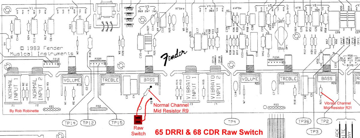
For the 65 Deluxe Reverb Reissue & 68 Custom Deluxe Reverb the Mid tone resistors are Normal Channel R9, Vibrato Channel R21 (at far right). The circuit board has these parts labeled. The resistors are mounted next to the Bass tone pots. Disconnect one end of resistor R9 and bend it to one side. Connect the Raw switch to the free end of R9 and the empty R9 mounting pad.
If your AB763 amp has a Mid tone pot then you don't need the 6.8k resistor at all. Just run the Mid pot's ground wire (on the left Mid pot terminal) to a Raw switch terminal and the other switch terminal to ground. The switch will now interrupt the tone stack's ground.
My preferred option for amps with a Mid tone pot is to simply replace the 10KA (audio or log) Mid pot with a 25KA or even 100KA pot (I prefer the 100KA). When you turn the Mid knob higher it will act as a "Raw" control, boosting the signal and removing the mid scoop.
I had one modder get an oscillation when he bypassed his tone stack with a raw switch. The extra gain from removing the lossy tone stack was enough to cause a downstream gain stage to freak out. He solved the problem by placing a 100k resistor across the switch terminals. The resistor reduces the gain jump when the switch is opened. You can use this resistor across the Raw switch to fine tune the level of gain added when the raw switch is turned on (opened).
Tone Stack Mods
Since both channels' tone stacks are identical you might want to consider changing one to offer different tone shaping options.
The Tone Stack is a series of three RC (resistance capacitance) audio filters that block three bands of audio frequencies. The Treble and Bass pots change the resistance of the RC audio filters to change the amount of signal filtered out. The blackface tone stack is a passive filter so it cannot boost any frequency band, it can only remove parts of the guitar audio signal. Note the Treble pot is wired as a variable voltage divider (potentiometer) while the Bass pot is wired as a variable resistor (the input and wiper terminals are tied together). In AB763 amps with a Mid pot it is a 10KA (audio or log) wired as a variable resistor.
Be aware that tone stack mods can affect "Fender Shimmer." When an AC audio signal enters a capacitor there is a slight delay as the cap fills and drains. This delay is called "phase shift". The larger the cap value the more delay so bass frequencies are phase shifted more than treble frequencies in the AB763 tone stack. Fender Shimmer is caused by this differing phase shift between treble (goes through a tiny 250pF treble cap) and bass (goes through large .1uF cap). The shimmer occurs where the treble and bass frequencies overlap--the mid highs to the mid lows. The treble control acts as a mixer for the treble and bass and maximum shimmer will occur near the treble control mid point when bass and treble are most balanced. The effect is similar to two guitars playing, one playing treble and one playing bass and they are slightly out of time which creates a nice, fat mid frequency tone. As guitar notes decay their harmonic overtones cause varying amounts of phase shift through the tone stack which causes the actual wavering "shimmer" effect. The greater the difference between the treble and bass capacitance values, the greater the shimmer effect. Blackface AB763 tone stacks with their large .1uF bass caps, tiny 250pF treble caps and 100k tone slope resistors seem to work best at maximizing shimmer. A lower 56k tone slope resistor raises the point of maximum shimmer a full octave. AB763 tone stack Fender Shimmer is one of the main reasons blackface amps are considered the high water mark of Fender amps. The shimmer added the missing ingredient needed to make the then new solid body electric guitar sound its best.
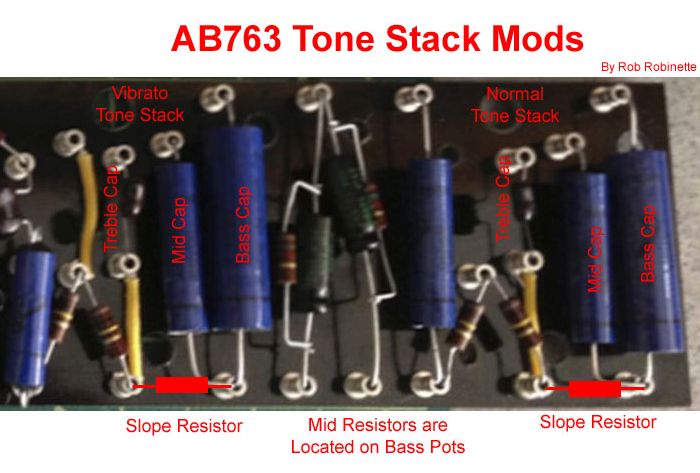
The AB763 Tone Stacks
Both channels' tone stacks are identical. The stacks' output flows directly into the Volume pot.
A common mod is to replace the 100k Tone Slope (yes, that's where he got his name) resistor with a 56k or even 33k which changes the way the tone controls operate. Others prefer a 150k Tone Slope. Keep in mind a lower Tone Slope resistor will increase the load of the tone stack and reduce gain.
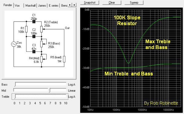
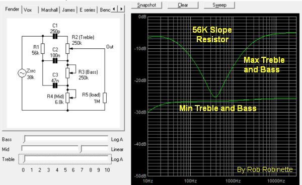
Standard 100k Tone Slope resistor on the left, 56k on the right. The effect is subtle but some prefer the 56k slope. Notice how the max bass and treble are balanced on the right with the 56k slope resistor. The 56k also boosts the midrange by 2.5dB. I'm a fan of the 56k tone slope resistor.
Another common mod is replacing the Tone Stack's 250pF treble tone cap with a 500pF which will extend the treble controls reach into the mid frequencies.
The reissue 68 Custom Deluxe Reverb uses a .02uF Mid cap instead of the AB763 standard .047uF. You can see the difference between the .047 and .02uF Mid cap in this chart:
Tone Stack Mid Cap Change
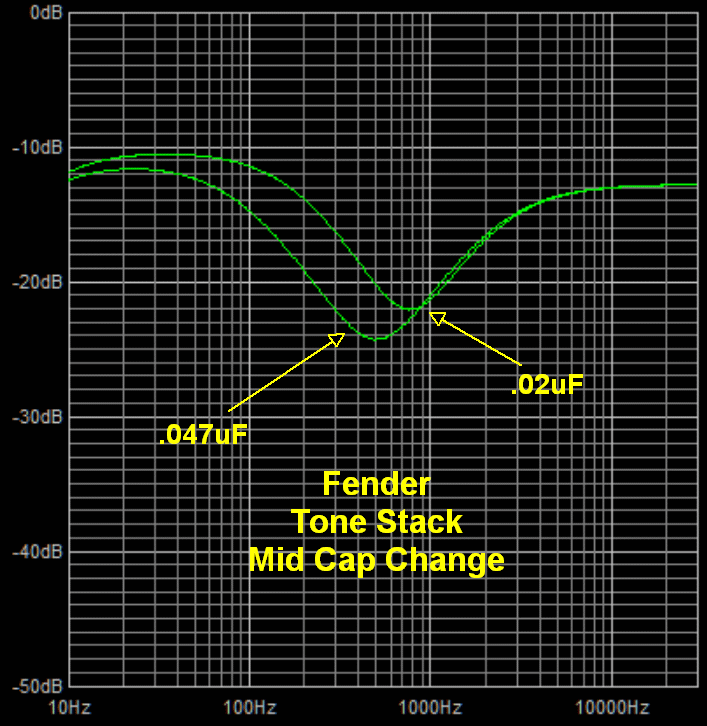
The Custom channel's reduced .02uF middle cap shifts the "mid" frequency band higher and reduces the mid scoop by over 2dB.
The 68 Custom Deluxe Reverb also has an 18k resistor between the Bass pot and 6.8k Mid resistor. The 18k resistor works as a minimum bass setting and keeps the bass from falling off a cliff as you approach the Bass pot's minimum setting. It makes setting low bass settings easier and more precise but it does limit you to how low you can set the bass.
If you are considering modifying the tone stack I recommend you download the free Duncan Amps Tone Stack Calculator so you can see graphically what the modifications do and how the Treble and Bass pots will react to the new component values.
Duncan Amps Tone Stack Calculator
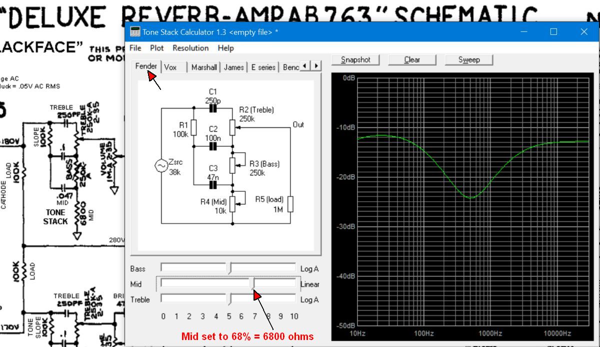
Once you get the Tone Stack Calculator running click on the Tone Stack Calculator's "Fender" tab at upper left. By setting the Mid slider (bottom left) to 68% you get 6800 ohms to equal the Deluxe Reverb's fixed 6800 ohm Mid resistor. You can double-click any component in the tone stack schematic to change its value so it's easy to see what happens to the control movements when you change the 100k slope resistor to 56k or adjust the value of the Mid resistor. The frequency response graph on the right will change as you alter component values or move the Bass and Treble pot sliders (at bottom left). Just playing with the pot sliders and watching the graph will tell you a lot about the interactive nature of the TMB (treble mid bass) tone stack. The Tone Stack Calculator is a very cool tool.
If you do install the Tone Stack Calculator be sure and see how a 25KL and 100KL Mid pot can act as a "Raw" control and boost the signal compared to a 6.8k resistor or 10KA pot.
Change the tone stack caps and resistors to suit your taste.
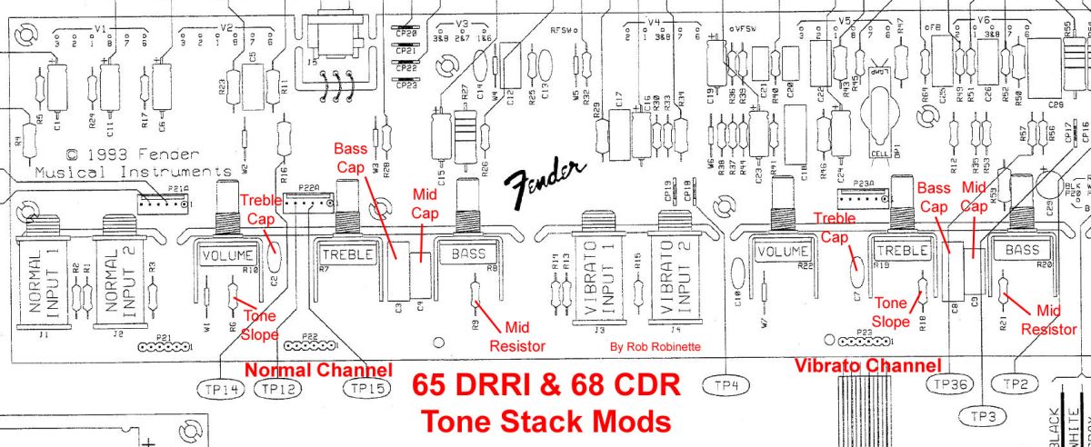
65 Deluxe Reverb Reissue & 68 Custom Deluxe Reverb Tone Stack Part Numbers:
Normal or Custom Channel Tone Stack
Tone Slope R6, Treble cap C2, Bass cap C3, Mid cap C4, Mid resistor R9
Vibrato or Vintage Channel Tone Stack
Tone Slope R18, Treble cap C7, Bass cap C8, Mid cap C9, Mid resistor R21
These part numbers are marked on the circuit board.
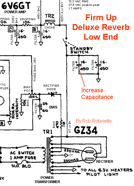
Firm Up the Deluxe Reverb's Loose Low End
The AB763 Deluxe Reverb and non-reverb Deluxe are infamous for their flabby low end that can lead to "farting out" at high volume. You can firm them up and make their tone more like their larger AB763 siblings by upping the value of the first filter capacitor. The filter capacitors are also known as reservoir caps because they store power that can be used when called upon by low frequency guitar notes and power chords.
Another more extensive modification option is to upgrade the power transformer but either of these mods will decrease the amp's touch sensitivity, playability and charm so it's not for everyone. I recommend you try the larger filter cap before messing with the power transformer.
WARNING: The first two Deluxe Reverb filter caps can hold their full charge if the amp is shut down with the Standby switch in Standby (disconnected). You MUST check for voltage at all the filter caps before trying this mod. If voltage above 25 volts is present then turn the amp on and make the amp ready to play by closing the Standby switch then turn the amp off. This should drain the filter caps but again, you MUST verify there is no voltage present with a volt meter.
You can temporarily clip in a parallel 16 or 32uF 450v (or higher voltage) cap to see if you like this mod. The higher the uF value the more the amp's character will change but you don't want the total capacitance of the first two caps to exceed 60uF which is the limit for the Deluxe Reverb's rectifier. If you don't want to try multiple caps I recommend you go with a 32uF. Alligator clip the new cap's + terminal to the first large cap's + terminal and connect the - to -. The filter capacitors are located in a "dog house" next to the output transformer and you'll have to remove the chassis from the cab to access it. Be careful removing the dog house cover because the caps might be charged with 430 volts. With the temporary cap clipped in the first filter stage will be equal to all three caps added together (16uF + 16uF + 16uF = 48uF) If you like the mod then replace the first large cap with your desired larger value cap.
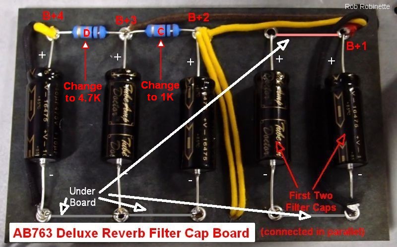
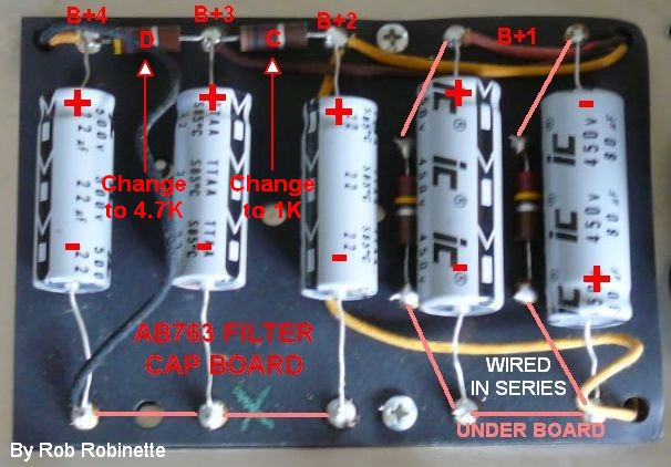
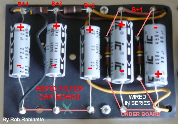
AB763 Deluxe Reverb Filter Cap Board

First two filter caps on the right are connected in parallel. All of these caps would be 16uF from the factory. You don't want the total capacitance of the first two caps to exceed the rectifier's 60uF limit. Note the two black ground wires connected to the bottom right and bottom left. The right ground wire is the power amp ground and the left is the preamp ground.
The 65 DRRI & 68 CDR's first two filter caps are 220uF 100v and 47uF 500v connected in series which is equivalent to a 38.7uF 600v capacitor. The 220uF cap has a 100k 1/2 watt bleeder and the 47uF has a 47k bleeder. A good upgrade is to replace the first two caps with 100uF 350v (or higher voltage) paired with 220k 1/2 watt resistors for an equivalent of 50uF 700v.
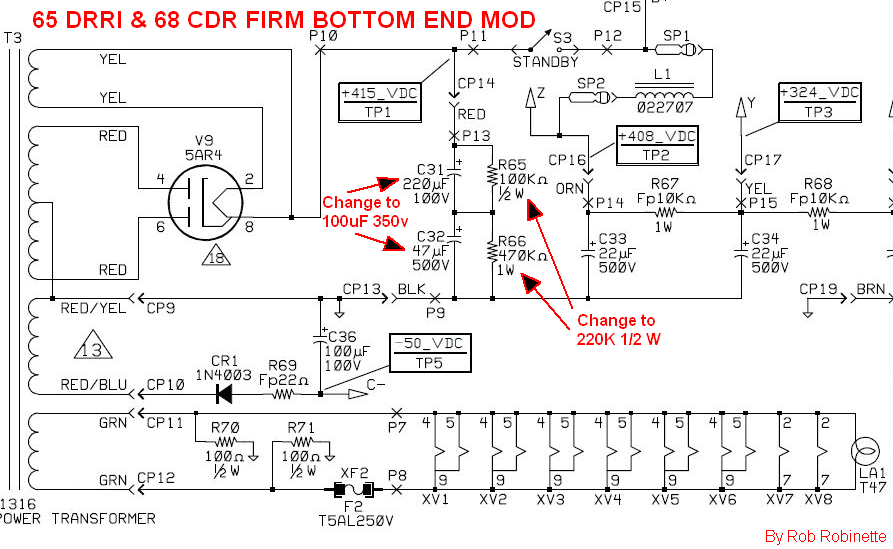
First two series caps on the right with their bleeder resistors above them.
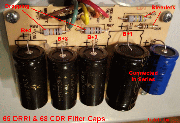
The other AB763 amps first two caps are 70uF 350v filter caps connected in series. These two caps are equivalent to a single 35uF 700v capacitor. One of the first two caps is upside down and they are connected + to -. They are accompanied by a 220k 1 watt bleeder resistor connected across each cap. These caps can also be upgraded to 100uF 350v (or higher voltage) for a little more power reserve.
AB763 Filter Cap Doghouse Board
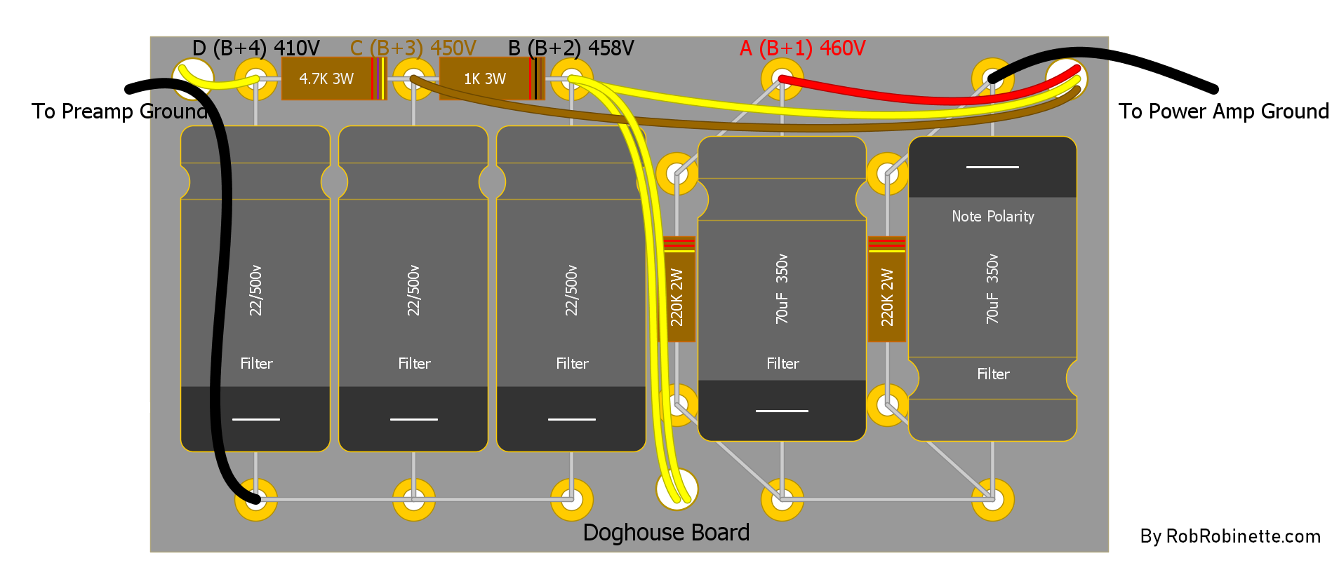
The first two caps on right are wired + to - in series, You must get the polarity right on these two caps. Note the two under board jumpers on the bottom of the board. From the factory the caps are from right to left: 70uF 350v, 70uF 350v, 20uF 350v, 20uF 350v, 20uF 350v. Note the two black ground wires, one connected at bottom left (preamp ground) and one connected at top right (power amp ground).
Add Tremolo to Both Channels
You simply need to move the yellow tremolo wire that runs from the Tremolo Intensity pot right terminal to the Vibrato channel 220k mixing resistor to after the mixing resistors--where both 220k mixing resistors join together. The tremolo wire connects to the Vibrato channel mixing resistor under the circuit board. If you don't want to lift the board to disconnect the tremolo wire you can disconnect it at the Tremolo Intensity pot and then run a new wire from the intensity pot to the two Mixing resistors. My annotated Band-Master layout says "Inject Tremolo" at "point Y" (below, center of layout). Move the yellow tremolo wire that runs from the Intensity pot to point Y to the other end of the mixing resistor.
Tremolo is injected at point Y (center of layout) using the yellow wire from the Intensity Pot right terminal. The connection point is marked in red "Inject Tremolo" label. Simply move that wire from the top of the 220k Mixing resistor to the bottom of the same resistor.
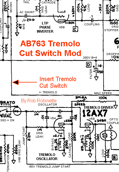
Tremolo Cut Switch Mod
This SPST ON/OFF mini switch completely disconnects the Tremolo circuit which will boost the guitar signal because the tremolo intensity pot places a load on the guitar audio signal. I like to orient the Tremolo Cut switch so that down is Tremolo off (switch open) and up is Tremolo on.
You can also replace the Tremolo Intensity pot with a 50KRA (reverse audio) push-pull pot. I purchased a 50KRA pot with an off position when you turn the dial full down from Vintage Amp Repair's ebay store.
50KRA Tremolo Intensity Pot With Off Position
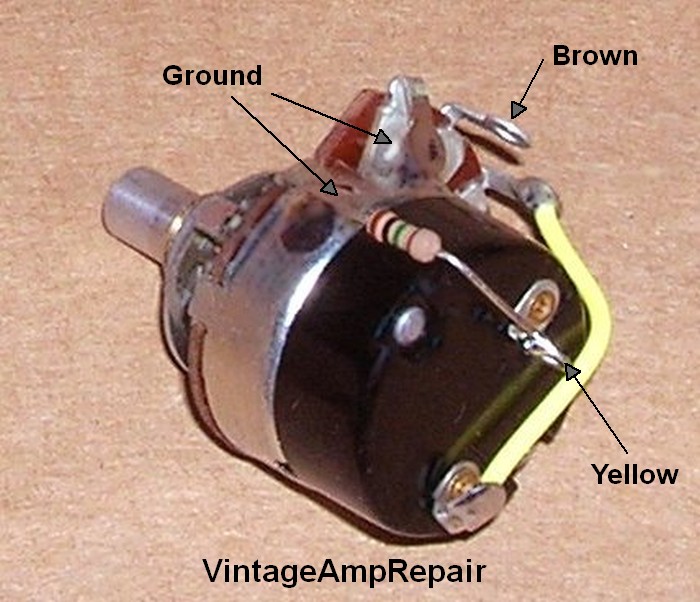
Photo by Randy Adkins, Vintage Amp Repair.
No one sells a 50KRA push-pull pot but you can make one by purchasing a common 250KA (non-reverse audio) push-pull pot and a 50KRA pot, then swap the 50KRA disc into the push-pull pot. I like to wire the push-pull switch pull-on but if you are a heavy tremolo user you can wire it pull-off .
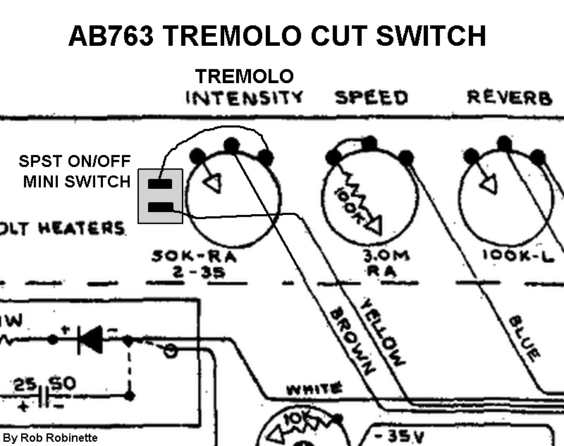
Splice in a SPST ON/OFF mini switch in the Tremolo Intensity pot's yellow (input) wire to completely disconnect the tremolo circuit.
To prevent the switch from popping when you engage tremolo you can place a 1M 1/4 watt resistor connected to ground (back of the pot) on one end and to the switch terminal that the yellow wire connects to.
This mod is a little more difficult in the 65 Deluxe Reverb Reissue & 68 Custom Deluxe Reverb because there is no wire, only a trace between the Tremolo Intensity pot and the 220k Vibrato Channel Mixing resistor R35 so you must cut the trace and bridge the cut with the Tremolo Cut switch.
You can also reduce the tremolo circuit load and boost gain by replacing the stock 50K-RA (reverse audio) Tremolo Intensity pot with a 100K-RA pot.
Slow the Tremolo
This is a pretty common mod that allows a slower tremolo which I really like. The tremolo circuit has three disk capacitors. Two are .01uF and the other is .02uF. Replace the two .01uF caps with .02uF 400v (or higher voltage) to slow the tremolo. Many people like to use Orange Drop caps in the tremolo oscillator.
If after this mod you would like a faster maximum tremolo speed you can reduce the size of the 100k "Max Speed" resistor located on the Tremolo Speed pot.
This mod puts a little more strain on the V5 tremolo tube so if the tremolo stops working after changing the two caps just install a fresh 12AX7.
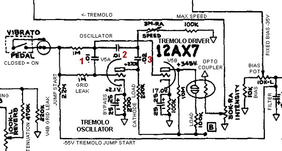
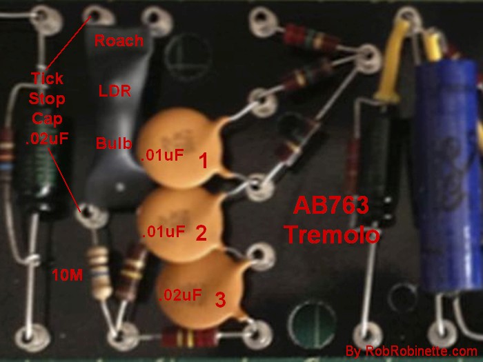
Disk cap numbers 1, 2 and 3 match the numbers in the schematic above. Replace #1 and #2 with .02uF 400v caps.
Stop Tremolo Ticking
The very strong tremolo oscillator signal can induce ticking into the amp's signal stream. First try to separate the tremolo driver plate (V5 pin 6) wire from any grid wires to stop the ticking. Pay close attention to the nearby V6A phase inverter grid (pin 2) wire.
Another option is to use a shielded cable like RG174 for the tremolo driver plate wire (V5 pin 6) to stop the transmission of the tremolo signal. This is almost a 100% fix for tremolo ticking. Ground the cable shield at only one end (either end) to prevent a ground loop.
If the above don't work then adding a .01uF 600v mylar cap to the tremolo roach should stop it.
Add a .01uF 600v (or higher voltage) mylar cap across the left side of the tremolo roach to cure tremolo tick. I now recommend a .01uF cap.
Fender service bulletin #9.
The ticking caused by the Vibrato is caused by improper lead dress. It can almost be "cured" by connecting a .01 mfd 600 volt Mylar capacitor on the 10 meg ohm resistor in the vibrato circuit. This resistor is located on the parts panel. If present, remove the capacitor in parallel with the 10 meg ohm resistor (old modification). [Rob recommends doing the lead dress changes in 1 & 2 below]
In other words, run the cap from the junction of the 10 meg resistor and the opto-isolator to ground [as in photo above].
If this does not produce the desired results, then the leads should be dressed as follows and excessive lengths shortened. [Shortening the leads should be your last resort]
1. Dress the leads to the vibrato speed and intensity controls away from the tone controls and filter leads. [Run the vibrato leads half-way between the tone control wires and filter cap wires]
2. "Bunch" the leads to the components on the parts panel which connect to the tube socket of the V5 7025 (12AX7) vibrato tube. [They carry a very strong signal]
Tremolo Always On RCA Plug
Blackface amps have a female RCA jack for the tremolo foot switch. Tremolo is turned on when the footswitch is closed. This little shorted male RCA plug will turn on the tremolo without having to plug in the tremolo footswitch. I like to keep mine in all the time. The $1 Switchcraft 3501MX RCA plug is a perfect fit with a long center connector.
Switchcraft 3501MX RCA Plug
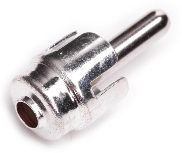
To short the plug insert a bare wire all the way through the connector--there's a hole in the end of the prong so run the wire all the way through then solder both ends of the wire to the plug. Be generous with the solder. Trim the wire flush at both ends and you're done.
Power Tube Grid Leak Mod
If you regularly push your AB763 amp hard into distortion then reducing the power tube grid leak resistors from the Fender standard 220k, down to the Marshall standard 100k 1/2 watt can sweeten the power tube overdrive tone. Doing this reduces the likelihood of blocking distortion because it reduces the charge and discharge time of the coupling cap between the phase inverter and the power tubes. The lower value grid leaks also reduce the gain from the phase inverter which also reduces the possibility of blocking distortion. See Tube Guitar Amplifier Overdrive for more info on blocking distortion.


The 220k 1/2 watt power tube grid leak resistors are on the far left end of the circuit board.
Add an AB763 Reverb Dwell Control
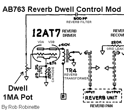
Simply replace the 12AT7 1M grid leak resistor with a 1MA pot. The Dwell control is a reverb circuit master volume.
12AT7 1M grid leak resistor clipped or removed. 1MA pot wired in its place.
The Reverb driver 1M grid leak works with the 500pF Reverb Filter cap to form a CR (capacitance-resistance) high pass filter with a corner freq of 318Hz (everything below 318Hz is cut). By replacing the 1M grid leak with a 1MA pot you will not only cut the amount of guitar signal entering the reverb driver as you turn down the Dwell pot but you will lower the CR corner freq as well which will allow more low freqs into the reverb circuit.
Place your dwell pot or trimmer wherever you want. Remove the 1M resistor. Wire the pot's left terminal to any ground. Wire the right terminal to the now empty right resistor eyelet (or turret). Wire the pot's center terminal (wiper) to V3 (12AT7) pin 7.
Channel Mixing Resistor Bright Caps Mod
Putting 500pF bright caps around the 220k Channel Mixing resistors will slightly brighten the tone of the modified channel. You can do one or both channels. If you only want to do one then I recommend doing the Vibrato channel since it is the brighter of the two channels. You can alligator clip the cap in place temporarily to see if you like the mod.
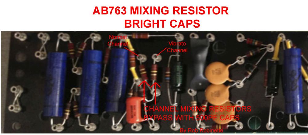
The 220k Channel Mixing resistor on the left is the Normal Channel's, the Vibrato Channel's resistor is on the right. Original photo by John Chabalko.
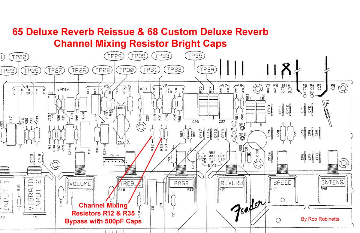
For the 65 Deluxe Reverb Reissue & 68 Custom Deluxe Reverb the Normal Channel Mixing resistor is R12. The Vibrato Channel Mixing resistor is R35. The circuit board has these parts labeled.
Adjust Reverb Level Mod
If you want to change how quickly reverb comes in as you turn the reverb pot then this mod is for you. At the output of the Reverb circuit the wet reverb signal flows through the Reverb pot, then through a 470k Reverb Attenuation resistor that forms a voltage divider with the following V4B (3rd stage preamp) 220k Grid Leak resistor and dumps 68% of the wet reverb signal to ground. You can tweak the reverb output level by changing the 470k Reverb Attenuation resistor. To increase the max reverb level replace it with a 220k and the attenuation drops to 50% and 110k will give 33% attenuation. Replacing the resistor with a jumper (or bypassing the resistor) will give 0% attenuation.
You can also go the other way and decrease the wet signal strength by upping the Reverb Attenuation resistor value to 680k for 24% attenuation or 1M for 82%, or 1.5M like on the 68 Custom Deluxe Reverb, but before you change the resistor value try a 12AU7 in the V3 Reverb Driver socket in place of the standard 12AT7. You might be happy with the cut in reverb signal with just a simple tube swap.
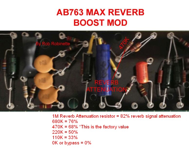
Decreasing the value of the 470k Reverb Attenuation resistor will boost the wet reverb signal level. Increasing the value will decrease the wet signal.
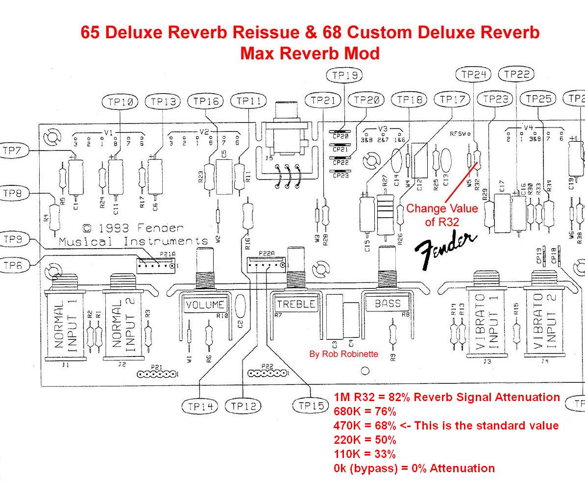
For the 65 Deluxe Reverb Reissue the Reverb Attenuation resistor is R32. The 68 Custom Deluxe Reverb has a 1.5M R32 resistor. The circuit boards have this part labeled.
Reduce Ice Pick Highs
If your particular speakers are giving you too many 'ice pick' highs simply adding a 100pF Mica capacitor across the feedback resistor will filter out some very high freqs that can cause ice pick highs. The cap allows high freqs to go around the feedback resistor so they are used for feedback which will reduce them from the amp's output. This is a nice, subtle mod that won't screw up your AB763's perfect tone. It's easy to use alligator clips to clip the cap in place temporarily to see if you like the mod. If you would like to cut even more highs than the 100pF cap, you can go all the way up to a .022uF cap to lower the filter's cutoff freq so more mid-high freqs would be cut. There's a small chance the Ice Pick Cap can induce oscillation at high volume. If that happens you can put a 4.7k resistor in series with the cap to reduce the very high frequencies that cause oscillation.
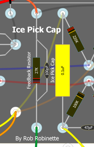
This is an Ice Pick Cap on a 5F6A Bassman but it works the same way in the AB763. Just put the cap around the 820 ohm Negative Feedback resistor.
Extra Bias Filter Cap Mod
This simple mod can reduce hum from the bias circuit. This cap was added to silverface amps for hum reduction.
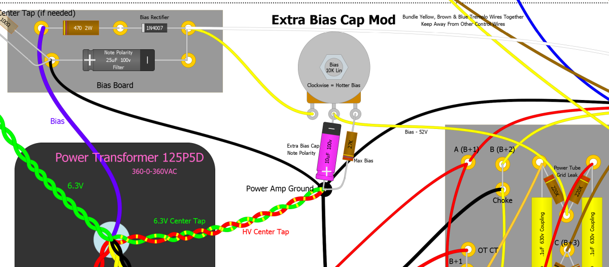
Extra 10uF cap from bias pot wiper to ground. Note the cap polarity, positive + to ground because the circuit deals with negative voltage.
Reduce Resistor Hiss Mod
Replace all the signal resistors (especially 1M input, plate load, grid leak and grid stopper resistors) with metal film resistors like the Vishay RN65 for less noise (hiss). Most AB763 kits use period correct carbon composition resistors but metal film resistors generate 1/10th the noise of carbon comp. In reality resistor hiss is usually drowned out by filament heater hum and power supply ripple so this won't be a dramatic improvement but every little bit helps with noise suppression. If you want to be thorough then replace every resistor except for the higher watt rated voltage dropping resistors located in the capacitor "dog house" between the filter caps. I also like to leave the phase inverter 22k tail resistor and the 100k & 82K phase inverter plate load resistors carbon comp (1 watt preferred) to ensure "vintage" carbon comp tone without generating excess noise.
This is one of those mods that's much easier to implement during a new kit build.
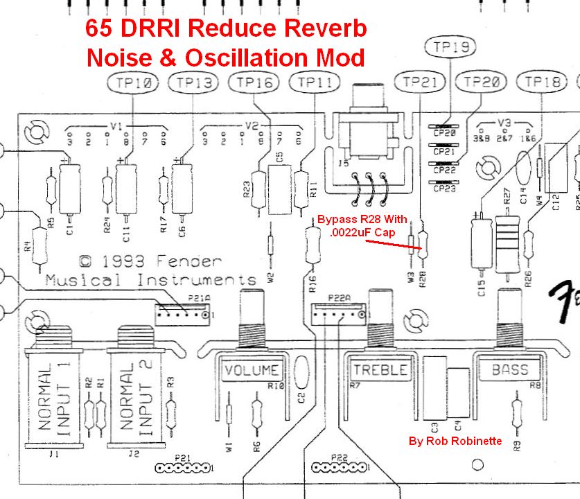
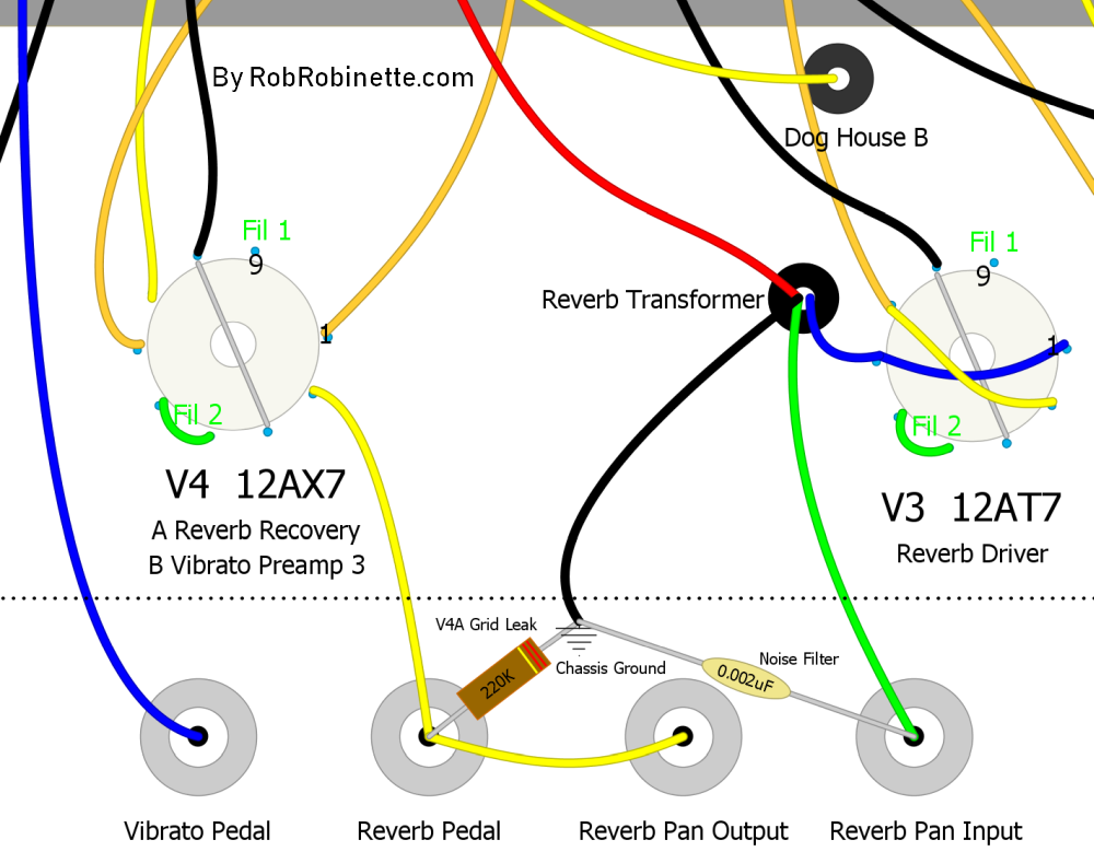
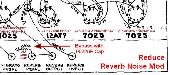
Reduce Reverb Noise & Oscillation
Fender added a .0022uF capacitor across the 220k V4A Reverb Recovery Grid Leak resistor in the A1172 silverface circuit. This cap can be seen in all Deluxe Reverbs through the Deluxe Reverb II. It's purpose is to filter out unneeded high frequencies which helps cut noise and prevent oscillation in the sensitive reverb circuit. If you have trouble with reverb in your amp this little cap can work wonders. The 68 Custom Deluxe Reverb already has a noise suppression cap in the reverb recovery circuit.
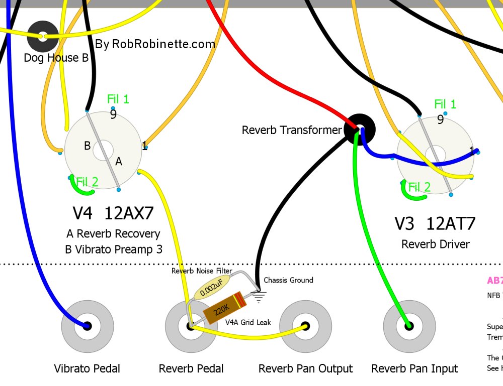
Solder a .0022uF bypass cap around the 220k V4A Grid Leak resistor.
Another Reverb Noise Fix From Fender
This .002uF cap from reverb pan input to ground was used in the AA1069 and AA270 silverface amps. I prefer the A1172 fix shown at top because it cleans up the pan input and output.
Darken the Reverb Tone
If your reverb tone is too bright you can add or adjust the bypass cap value shown in the above Reduce Reverb Noise & Oscillation mod. A .01uF (25v or higher) will audibly darken the reverb tone. You can play with that value to adjust the tone to your taste.
Solder a .01uF bypass cap around the 220k V4A Grid Leak resistor to darken the reverb tone.
Dumble AB763 Mods
I haven't tried any of the Dumble mods but I include them here for completeness.
Dumble Cool Mod + Boost Switch
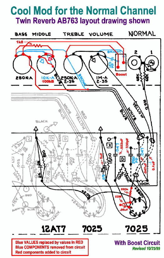
Turns the Bright Switch into a Boost Switch. Remove the blue stuff and replace it with the red. Note the Normal Channel tone stack's mid .047uF and bass .1uF caps are not changed even though they are shown in red.
These mods were designed to be coupled with an additional gain stage so they by themselves will alter the Normal Channel's tone but not really in the way intended. You may or may not like what they do but they should work really well with gain or boost pedals.
The Cool Mod lowers the value of the Normal Channel first gain stage cathode bypass cap from 25uF to 5uF to reduce the emphasis on lower bass frequencies which helps keep the overdrive tone tight.
The mod adds a 220k grid stopper resistor to the Normal Channel's second gain stage (V1B) which helps prevent blocking distortion which comes in handy when you add a gain stage between V1A and V1B like the original Dumble AB763 Mod did. The added grid stopper also helps when you hammer the amp with a big boost or gain pedal. Another option here is to parallel the new 220k grid stopper with a 390pF bright cap if you want to add some highs.
The Cool Mod adds a local negative feedback loop to the Normal Channel's second gain stage (V1B). It's negative feedback because the plate is 180 degrees out of phase with the grid. The mod connects V1B's plate back to the grid through a 22M resistor and .047uF (400v or higher) cap.
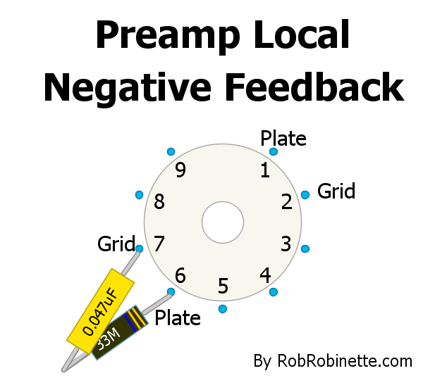
A 22M to 44M resistor and .047uF 400v+ cap connect the preamp grid and plate together to form a local negative feedback loop.
The mod can also be used on the "A" triode pins 1 and 2.Like most amplifier negative feedback loops this mod will reduce distortion, tighten the transition from clean to dirt and slightly reduce gain. At first blush I was going to recommend not using this mod on the first stage of amplification because if the cap fails as a short it could inject high voltage into the guitar circuitry but even if this does happen the large value feedback resistor will limit the current to 18 micro amps (.018 milliamp) or less so it's not a concern. This mod would be of relatively little use in the first gain stage anyway since it is rarely overdriven.
If this NFB loop tightens up the tone too much try a larger value resistor like a 44M. The larger the resistor the less negative feedback gets through to the grid. This is a pretty cool yet extremely simple circuit that should be experimented with in all high gain preamps.
The Cool Mod also reduces the size of the Normal Channel coupling cap by half, going from .047uF to .022uF to trim some unneeded low frequencies which will tighten up the overdrive tone.
The Cool Mod also alters the Normal Channel tone stack with a change from a 250pF to a 330pF Treble cap which boosts the mids and allows the Treble tone control to reach deeper into the mids. A 1.8k "minimum bass" resistor is added to the tone stack that keeps the bass from falling off a cliff as you approach the minimum Bass pot setting. The downside is it slightly limits how low you can set the bass. The 68 Custom Deluxe Reverb has an 18k minimum bass resistor in the same position. You can add this resistor to any AB763 by replacing the wire that runs between the Bass and Middle pots (or Middle resistor) with an 18k resistor.
The mod also replaces the 10KA (audio or log taper) Middle pot with a 100KB (linear) pot which acts as a "Raw Control." The first 1/10 of the Mid pot movement is equivalent to the entire original 10KA Mid pot. As you roll in more Mid control the mid scoop is removed and the signal is boosted across the frequency spectrum.
The Boost Switch works as a standard "Raw Switch" which lifts the tone stack's ground effectively removing it from the circuit which completely removes the famous blackface mid scoop and offers up a big boost in signal.
Dumble Cool Mod + Rock/Jazz Switch + Optional Separate Boost Switch
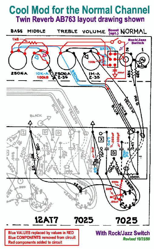
The Rock/Jazz Switch in the Jazz position filters out some bass and mid frequencies. Note the optional separate "Boost (opt.)" SPST (single post single throw) switch between the Volume pot and Input jack.
Dumble Cool Mod + Rock/Jazz Switch + Push-Pull Pot Boost Switch
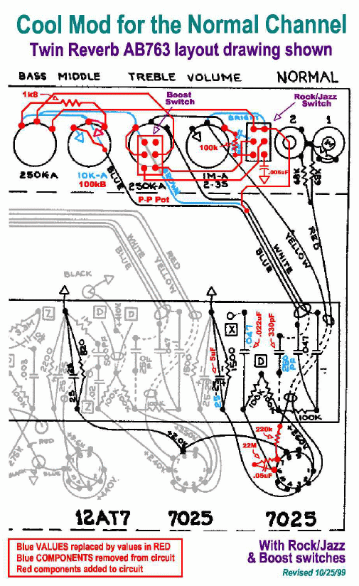
The only difference from above is the Boost Switch is shown on a 250KA (audio or log) push-pull Treble pot.
Replace the 2-Prong AC Receptacle with a 3-Prong
You can replace the 2-prong receptacle on the back of the amp with a 3-prong 160-2-N receptacle. This will allow you to use modern 3-prong accessories with the amp. The power cord's hot (black) wire should run to the receptacle's narrow prong and the neutral (white) wire should connect to the wide prong. The ground prong should be tied to the power cord's safety ground wire. I don't recommend connecting this receptacle after the mains fuse because you can blow the fuse if you plug in something that uses more than 2 amps.
3-Prong 160-2-N Receptacle
This is an easy bolt-in replacement available here.
Convert a Band-Master Into a Vibrolux, Tremolux, Pro, Concert or No-Reverb Vibroverb or Super Reverb
The Vibrolux and Vibroverb combos are much more sought after amps these days than the lowly Band-Master head but their differences are trivial and converting a Band-Master into any of the 2x6L6 AB763s is an easy mod. You can buy a $500 AB763 Band-Master head and place the chassis in a 1x12 cab for a Vibrolux; a 1x15 cab for a Pro or no-reverb Vibroverb; a 4x10 cab for a Concert or no-reverb Super Reverb and install a 4 ohm speaker load rated at a total of 75 watts or higher.
2x10 Band-Master Combo Conversion
To convert the Band-Master into a Vibrolux or Tremolux you need to replace the Band-Master's 4.7k B+4 power resistor (located in the "dog house") with a 10k 2 watt to match the Vibrolux's lower preamp voltages. If you want to simulate the Vibrolux tube rectifier in the Band-Master you can insert a 62 ohm 5 watt resistor between the rectifier and first filter cap to get the 10v drop and sag of a GZ34.
Band-Master Filter Cap Board
The filter cap board is located under the "dog house" cover outside the chassis next to the output transformer. Replace the resistor between the "B+4" and "B+3" label above with a 10k 2 watt resistor.
Next swap out the Band-Master's 500pF phase inverter coupling cap for the a .001uF (1000pF) 200v (or higher voltage).
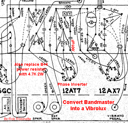
Replace the Band-Master's 500pF phase inverter coupling cap with a .001uF 200v.
To convert a Band-Master to a Pro, Concert or no-reverb Vibroverb the only mod required is the phase inverter coupling cap change shown above. You don't need to modify the power resistor. Another mod to consider for a Vibroverb conversion is to install a Tremolo Cut Switch which will boost the amp's gain to mimic the 3 preamp gain stage Vibroverb. For a Super Reverb or Concert conversion change out the two tone stack's mid caps for .022uF 200v (or higher voltage). I really like the JBL D130F 15" speaker, or Weber's version, the Ceramic California 15 (4 ohm, 80 watt, paper dome), for the Vibroverb.
It's true the Vibrolux and Vibroverb have an 8 ohm output transformer secondary where the Band-Master has a 4 ohm but that will make no difference if you connect a matching speaker.
Another 2x10 Band-Master Combo Conversion
Photo and mods by BobbyZ.
I'm a head amp fan so I usually leave my head amps in their original cab but there are several sources for nice blackface combo cabs to place your Band-Master chassis. The standards are 1x12 for the Vibrolux conversion, 1x15 for the Vibroverb and 4x10 for the Pro and Super Reverb. I've heard good things about Mojotone's cabs and Mather Cabs. If you order a cab be sure and tell them it's for a Band-Master chassis.
Convert a 65 Deluxe Reverb Reissue (DRRI) Into a 68 Custom Deluxe Reverb (68 CDR)
Differences between the 65 Deluxe Reverb Reissue and 68 Custom Deluxe Reverb:
British voiced 12” Celestion G12V-70 speaker.
Reverb and tremolo are available on both Vintage & Custom channels. On the 68 CDR they call the Vibrato Channel the "Vintage" Channel and they call the Normal Channel the "Custom" Channel. Both channels go through the third preamp gain stage V4B so both channels are now in phase so you can jumper channels for a thicker tone.
Negative feedback is cut in half by doubling the size of the NFB resistor. Less feedback thickens up the clean tone with extra harmonics, slows the transition from clean to dirt but adds some resistor hiss. Some users find the extra hiss objectionable. Personally I like the lower feedback of the 68 CDR and feel the hiss is worth the trouble.
Vintage (Vibrato) channel bright cap has been removed from the volume pot.
The reverb circuit uses a 1.5M vs 470k Reverb Attenuation resistor (R32) which adds attenuation and slows the action of the reverb pot as it's turned up making the control less twitchy.
The Custom (Normal) Channel's tone stack has a smaller .02 Mid cap and an extra 18k resistor between the Bass pot and Mid resistor. The smaller Mid caps shifts the mid band and mid scoop up frequency. The 18k resistor acts as a "Bass Floor" and keeps the bass from falling off a cliff as you approach minimum Bass pot settings but it limits how low you can set the bass. If you want to be able to set less bass then lower the value of the Bass Floor resistor. Some 68 CDR owners have jumpered around this resistor to allow lower bass settings so you may not want to add this resistor to your 65 DRRI.
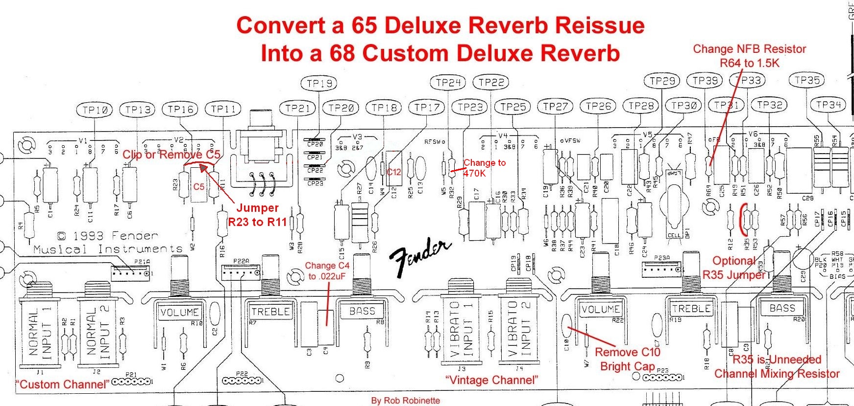
Click on the image to see the full size, readable layout.
Step 1. Do the very simple Normal Channel Reverb Mod. This mod is exactly how the 68 CDR sends the Custom (Normal) Channel through the reverb and tremolo effects and third preamp stage. You will also be able to jumper the channels together after this mod for a slightly fatter tone. If you think you may alter the voicing of one of the channels then I recommend you do the robrob Normal Channel Reverb Mod instead to add reverb and tremolo to the Normal Channel. The robrob Mod retains the Normal Channel's coupling cap so you can change its value to alter the Normal Channel's voice. For the 68 CDR style mod simply connect the top of Resistors R23 & R11 with a jumper wire and clip or remove cap C5 (both mods upper left in layout above).
Step 2. Change the Negative Feedback Resistor R64 to 1.5k or do the 3-Way Negative Feedback Switch Mod. The 3-Way mod has an 820 ohm and a 1.5k NFB resistors so you can select normal 65 DRRI feedback or no feedback or 68 CDR feedback.
Step 3. Remove or clip a leg of the Vibrato Channel Bright Cap C10 located next to the Vibrato Volume pot. You could also put the cap on a switch. Use a SPST mini switch to break the connection between the Bright cap and Volume pot center terminal.
Step 4. Modify the Normal Channel tone stack to match the 68 CDR Custom Channel. Change the Mid capacitor C4 to .022uF.
Step 5. Change the Reverb Attenuation Resistor R32 to 470k. This will add attenuation and slow the action of the reverb pot as it's turned up making the control less twitchy. This is a rather minor mod and can be skipped in my opinion.
The 68 CDR schematic calls the 18k 1/2 watt Bass Floor resistor R72. To insert the resistor you must cut the trace on the pot control board that runs from the Bass pot to the intersection of the 6.8k Mid resistor R9 and the C4 Mid cap. Then bridge the cut trace with the 18k resistor. If the 18k resistor limits your minimum bass setting too much you can try a smaller value resistor like a 12k. Some 68 CDR owners have removed this resistor so I do not recommend adding the R72 18k Bass Floor resistor to your 65 DRRI.
Speaker Suggestions for the AB763
Weber 12F150 Vintage American Voice, 12", ferrite magnet, 1.5 inch voice coil, light dope $114. Weber's and my recommendation for the blackface amps that use 12" speakers. 10F150 is my recommendation for blackface amps that use 10" speakers, $94. Both require a long, 50 hour break in unless you have Weber do their free break in service.
Weber Ceramic Signature 10" and 12" for the budget minded. Some actually prefer the Sigs to the more expensive 10F150 and 12F150. Four Sig 10's in a Super Reverb sound absolutely glorious.
The 68 Custom Deluxe Reverb comes with a British voiced 12” Celestion G12V-70 and the amp gets great reviews.
Eminence GA-SC64 Vintage American Voice, "Tones of 1964 still ring true in this vintage voiced speaker by seasoned amp guru George Alessandro. Well balanced from top to bottom, the GA-SC64’s warm, dynamic character lends itself to vintage amps as well as modern gain and distortion. The traditional build materials offer warmth, dynamics, low note articulation and proper distorted harmonic content layering."
Eminence Cannabis Rex "The Eminence Cannabis Rex guitar speaker lets your laid-back style come through. Clean and full, with lots of body and sparkle. Smokey smooth with high-end definition. Country, Jazz or Classical guitarists take notice."
JBL D120F Loud, clean, efficient but heavy and adds some mids the amps needs. Best defense against ham fisted drummers. You can always find a blown one and have it reconed.
Celestion 12M Greenback Warm and Woody with relatively early breakup.
Eminence GB128 Vintage British Voice, "The Eminence Legend GB128 guitar speaker helps clean up your act. Cleaner British voiced tone with a full low end, warm, throaty mids and a very open top end. Turn up the volume and turn back the clock."
The WGS ET65 is an amazing replacement speaker for Fender amps even before you consider its low low price. "The ET65's creamy lows blend with tight midrange and sparkling highs for some of the best tones ever created. This speaker is for classic rock, country, and blues. Upgrade from your Celestion™ G12-65."
Quad Power Tube 1/2 Power Switch
For quad power tube amps you can safely switch off two of the power tubes by breaking a pair of power tubes' cathode connection to ground. This will stop all current flow through the tubes and cut output by 50%. You won't get a 50% output volume cut but it will help tame these beasts.
You need to disconnect one tube from each side of the push-pull pairing. For example in the Fender Twin Reverb you would disconnect tubes V7 & V10 (see layout below).
A simple SPST (single post single throw) ON-OFF mini-toggle switch will do the job. Insert the switch between the power tubes' cathode (pin 8) ground wire. Switch closed is normal quad tube power, switch open will turn off two tubes.
For best tone and amp loading you should make a speaker impedance adjustment up one notch. Since current into the output transformer is cut in half we need twice the load on the transformer secondary to compensate. For example connect a 16 ohm speaker to an 8 ohm speaker jack but most amps will run fine with this amount of impedance mismatch.
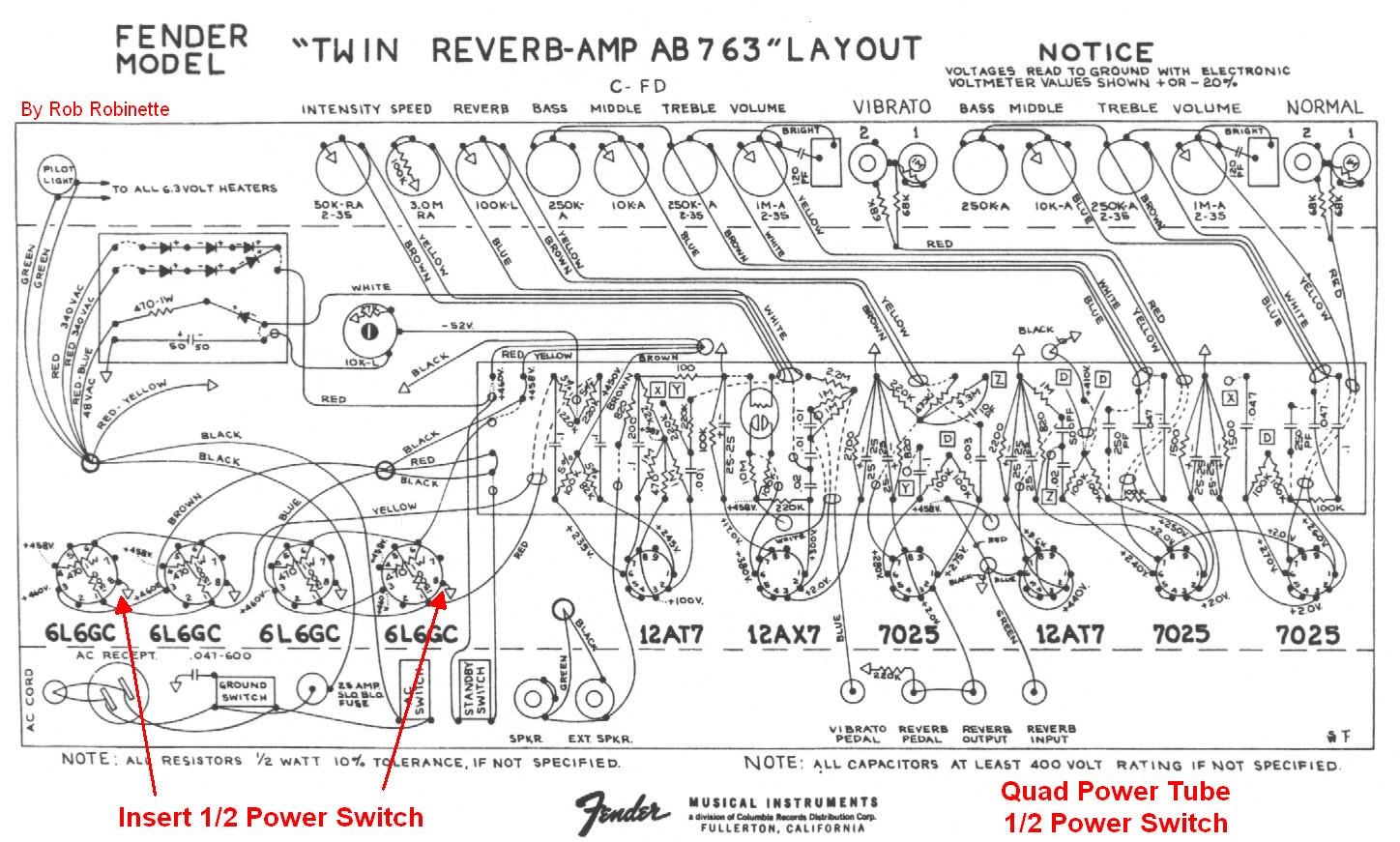
Insert ON-OFF switch between power tube socket pin 8 (cathode) and ground. Note how V7 and V8 share the blue output transformer wire--they are in parallel so we can turn off V7 with the cathode switch. The same goes for V9 and V10--they share the brown output transformer wire.
Preamp Tube Tweaks
Pull the Normal Channel preamp tube V1 and use the Vibrato Channel. Of course this assumes you don't use the Normal Channel because tube V1 is the Normal Channel first and second preamp stages. Pulling V1 changes the amp circuit because the V1B and V2B triodes share an 820 ohm cathode resistor. Two triodes sharing an 820 ohm cathode resistor is the equivalent of each triode having its own 1.5k resistor. If you remove V1 then the V2B (Vibrato Channel second gain stage) preamp goes from normal center bias to a warm bias with an 820 ohm cathode resistor. In other words pulling V1 is exactly like changing the Vibrato Channel second preamp gain stage from a 1.5k cathode resistor to an 820 ohm. This warm bias increases gain and makes creamy sounding asymmetric clipping more likely. Removing V1 will also raise the plate voltage on all the preamp gain stages which adds a some gain also. Removing V1 works really well with hot boost pedals or even hot humbucker guitars.
Replace V1 or V2 with a 12AY7. You can go the opposite direction and reduce preamp gain by replacing the 12AX7 in V1 (Normal Channel) or V2 (Vibrato Channel) with a lower gain 12AY7. The 12AY7 was used as the first gain stage for many of the tweed amps and will offer up more clean headroom because its lower gain will reduce preamp distortion. This swap can really shift the distortion balance between preamp and power amp to favor power tube distortion when you combine it with the V6 phase inverter tube change as discussed in the next paragraph.
Try a 12AX7 in the V6 Phase Inverter for more power tube distortion. The 12AX7's extra gain will hit the power tubes with a hotter signal. This is a way to shift the AB763's preamp/poweramp distortion balance toward the power tubes. To give it a try just move the V1 12AX7 into the V6 socket and use the Vibrato Channel.
Replace the V3 12AT7 Reverb Driver tube with a lower gain 12AU7 to give you more usable room on the Reverb Control. The Reverb pot can be a little touchy with a usable range from 0 to 3 or 4. A 12AU7 won't push the reverb circuit as hard so the usable range can extend up to 5 or 6 on the dial and make dialing in just the right amount of reverb easier. The lower gain 12AU7 can also reduce reverb circuit noise.
Another option to tame the reverb level is to install a 7247 or 12DW7 tube in V4. These tubes are dual triodes but the A triode is a 12AU7 equivalent with lower gain than a 12AX7. The B triode is a 12AX7 equivalent so the V4B preamp stage stays at full gain. Decreasing the reverb recovery's gain makes the Reverb Control less touchy, somehow enhances the reverb tone and can decrease reverb noise.
Run 6V6 Power Tubes In 6L6 Amps
Running 6V6 power tubes in a big bottle AB763 will give you small bottle tone but with lots more power tube overdrive because the preamp is tuned to hit the phase inverter and power tubes harder than in the small bottle AB763s.
To compensate for the different power tube impedance we need to adjust the speaker impedance. Since the little 6V6s put out much less current they need a higher impedance load. For a big bottle amp with a 4 ohm output transformer secondary we need to connect an 8 ohm speaker. With a 2 ohm secondary we need a 4 ohm speaker or with an 8 ohm secondary we need a 16 ohm speaker.
JJ 6V6S power tubes are good for 500 plate volts so they can handle 6L6 voltage but for normal 6V6 tubes you must do something to lower the plate voltage to keep from frying them. For amps with tube rectifiers you can plug in a lower rated rectifier like the 5R4 (less sag) or 5Y3 (more sag) to bring down the voltage. For amps with solid state rectifiers like the Twin Reverb and Single and Dual Showman you can plug the amp into a variac and turn down the amp's input voltage. A bucking transformer at its lowest setting may also do the job.
You may also need to adjust the bias after installing the 6V6 tubes. See this to measure and adjust the bias.
Run 6L6 Power Tubes In 6V6 Amps
You can get a different tone from the small bottle Deluxe and Deluxe Reverb amps by installing 6L6 power tubes but the power and output transformers can't supply all the extra current needed to actually get much more volume at the speaker. Running 6L6 tubes will stress the transformers so I don't recommend it but if you want to give it a try then you should make a change to the speaker load to compensate for the different power tube impedance. Just use a 4 ohm speaker with the Deluxe and Deluxe Reverb's 8 ohm secondary.
The amp may sound more sterile because the low voltage preamp and phase inverter are tuned to drive the 6V6 so you'll get less power tube distortion. If you plan to permanently swap to the 6L6 then I recommend you raise the preamp and phase inverter voltage to better drive the 6L6 power tubes.
Everyone that moves up from small bottle power tubes to large should measure their 6.3v heater voltage and make sure it's not 10% lower than spec (lower than 5.7v). The extra current draw of the big tubes can over tax some power transformers.
Keep an eye on your power transformer's temperature when running the big power tubes but be careful because the transformer can get hot enough to burn your fingers. I use an infra red no-touch thermometer to monitor amp component temperatures. Take a measurement with the normal 6V6 tubes so you have a baseline temp to compare to how hot it gets with the big tubes.
Replacing the GZ34 tube rectifier with a solid state rectifier like the plug-n-play Weber WS1 Copper Cap will supply the amp with a little more voltage and current to better drive the big 6L6 tubes.
You will probably need to turn up the bias to get the most from your 6L6 tubes. See this to measure and adjust the bias.
Run 2 Power Tubes in a 4 Power Tube Amp
Many push-pull amps designed to run 4 power tubes can be run with 2 power tubes to cut the output power in half. But since the output transformer was designed to load the current put out by 4 power tubes we need to make an adjustment on the speaker end to load 2 tubes properly. Since 2 power tubes put out half the current of 4 tubes we need to double the speaker impedance so 2 tubes feel the same load as when 4 tubes are used. For example your amp is designed to run an 8 ohm speaker with 4 tubes like the AB763 Blackface Single Showman so it will need a 16 ohm speaker when run with 2 power tubes.
To run two power tubes you pull the two outside power tubes, which in the Twin Reverb are V7 and V10. In the Single and Dual Showman the outside power tubes are V5 and V8 (tube numbering starts with the first preamp tube on the far right).
The plate voltage will be higher with only two tubes pulling current through the power supply so you may need to adjust the amp's bias. See this to measure and adjust the bias.
Run 2 6V6 Power Tubes in a 4x6L6 Amp
As stated above we need to up the speaker impedance when substituting 6V6 tubes in a 6L6 amp and we also need to up the impedance when running only 2 power tubes in a 4 tube amp so we need to take two steps up in speaker impedance to run 2 6V6 power tubes in an amp designed for 4 6L6 tubes. For an amp with a 2 ohm secondary we would need an 8 ohm speaker, a 4 ohm secondary needs a 16 ohm speaker and an 8 ohm secondary would need 32 ohms of speaker load (two 16 ohm speakers wired in series). For example, the Twin Reverb has a 4 ohm output transformer secondary. It has two 8 ohm speakers wired in parallel to give the transformer its needed 4 ohm load. With two 6V6 tubes the amp will need a 16 ohm load which can be done by simply wiring the two speakers in series.
You must consider the power tube plate voltage when running 2 6V6 tubes. With only two small power tubes pulling current through the power supply all the voltages in the amp will be higher than normal. JJ 6V6S power tubes are good for over 500 plate volts so they can handle the Twin Reverb's voltage but for normal 6V6 tubes you must do something to lower the plate voltage to keep from frying them. For amps with tube rectifiers you can plug in a lower rated rectifier like the 5R4 (less sag) or 5Y3 (more sag) to bring down the voltage. For amps with solid state rectifiers like the Twin Reverb and Single and Dual Showman you can plug the amp into a variac and turn down the amp's input voltage. A bucking transformer at its lowest setting may also do the job.
To run two power tubes you pull the two outside power tubes, which in the Twin Reverb are V7 and V10. In the Single and Dual Showman the outside power tubes are V5 and V8 (tube numbering starts with the first preamp tube on the far right).
You will probably need to adjust the bias when running two 6V6 tubes. See this to measure and adjust the bias.
Hi/Low Input Switch
This switch allows you to use one input jack and select Hi or Low output. The switch inserts a 33k/33k voltage divider which dumps half the guitar audio signal to ground--just like a standard Fender Low Input jack. With the switch open you have the High Input and switch closed you get the Low.
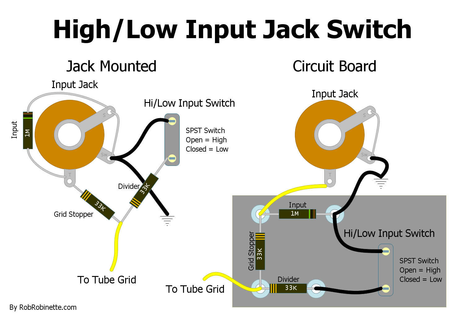
Jack mounted circuit on the left, circuit board version on the right. Download the high resolution pdf here and DIYLC file here.
In the High position input impedance is 1M and grid stopper resistance is 33k--exactly as the 5E3 Deluxe.
In the Low position input impedance is 62k (1M in parallel with 66k) and grid stopper resistance is 33k.
The factory 5E3 has a Low input impedance 138k and grid stopper resistance of 68k but this mod will give us a tone that's so close to factory that I'll buy you a case of beer if you can hear a difference.
Real World Voltages
Here's the voltages I measured on my bone-stock AB763 Band-Master:
AC Voltages
Wall: 125.4 Volts AC
Rectifier Input: 348VAC (Schematic lists the power transformer as 320VAC with 117v wall power)
Heaters: 7.1VAC Yes, that's too high, it should be 6.3VAC +/- 10% or 5.7v to 6.9v.
Bias supply tap: 61VAC
DC Voltages with 6L6GC Power Tubes biased to 67%
B+1: 465 with V5 plate 463, V6 plate 463 (Schematic lists 440v for B+1, plates and screens)
-48 bias on both grids for a bias of 67% of max dissipation.
B+2: 466 with a .65v drop across 470 ohm screen resistors for 1.4 milliamps of screen current (Schematic lists 440v B+2)
B+3: 455 with 237, 240 on phase inverter plates (Schematic lists B+3 of 430v, plates 225v)
106v at the phase inverter cathode-tail junction (Schematic lists 105.5v)
B+4 430 with V2 plates 290, V1 plates 285 (Schematic lists B+4 of 375v, plates 275v)
Voltages Using a Bucking Transformer
After getting these voltages I powered the amp through a bucking transformer to bring down all the voltages.
Wall dropped from 125.4VAC to 111v.
Rectifier input dropped from 348VAC to 309v.
Heaters dropped from 7.1VAC to 6.2v.
B+1 lowered from 465v DC to 416v, 49 volts lower than with straight 125.4 VAC wall power.
I highly recommend you run your older amps through a bucking transformer. The amp and tubes will last longer and sound more authentic.
"Blackface" a Silverface Amp
I blackfaced my 1969 AA1069 silverface Bandmaster Reverb (TFL5005D) into a 1963 AB763 blackface Vibroverb with just a few mods shown in red below. The .047 Bass cap, Phase Inverter Plate Load resistors and Power Tube Grid Leak resistors are the most important to tone.
All the Differences Between the AB763 Vibroverb and AA1069 Bandmaster Reverb
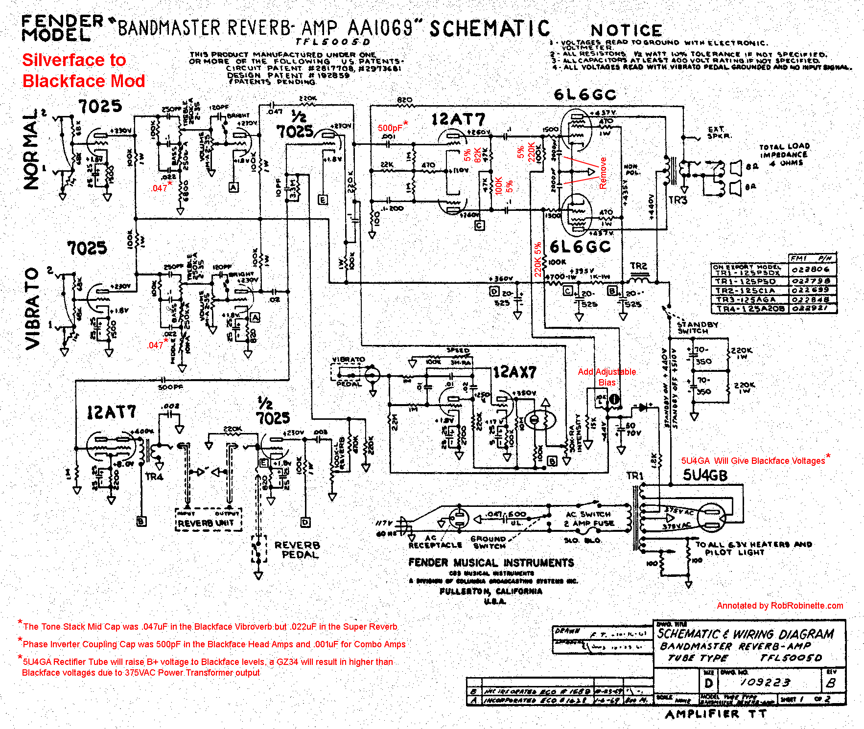
*The Tone Stack Mid Cap was .047uF in the Blackface Vibroverb but .022uF in the Super Reverb. I'm a fan of the .022uF Mid Cap.
*Note the Phase Inverter Coupling Cap is shown in red with an asterisk because Blackface head amps used a 500pF coupling cap and the combo amps used a .001uF like this silverface amp. Fender used the smaller cap to trim some bass because the matching blackface extension cabs were closed back and had extended bass response. If you play mostly clean or use mostly open back cabs the .001uF cap would probably be best, but if you play a lot of overdrive the 500pF might be best for a tighter overdrive tone.
*Using a 5U4GA Rectifier tube will bump the B+ voltage up to AB763 Vibroverb levels. Using a GZ34 like the Vibroverb will boost the B+ well beyond the Vibroverb levels because the Bandmaster Reverb's Power Transformer puts out 15 more volts than the Vibroverb.
Replace the Phase Inverter Plate Load resistors with 82K (V6A) and 100K (V6B) 1/2 watt rating) resistors.
Replace the Power Tube Grid Leak resistors with 220K 1/2 watt resistors.
Remove or clip the Stability Caps connected to the Power Tube Grids (pin 5).
I recommend keeping the AA1069 Bias Balance circuit and just add a 25k Bias pot so you have both adjustability to set the bias and a Bias Balance pot to match bias between the two power tubes.
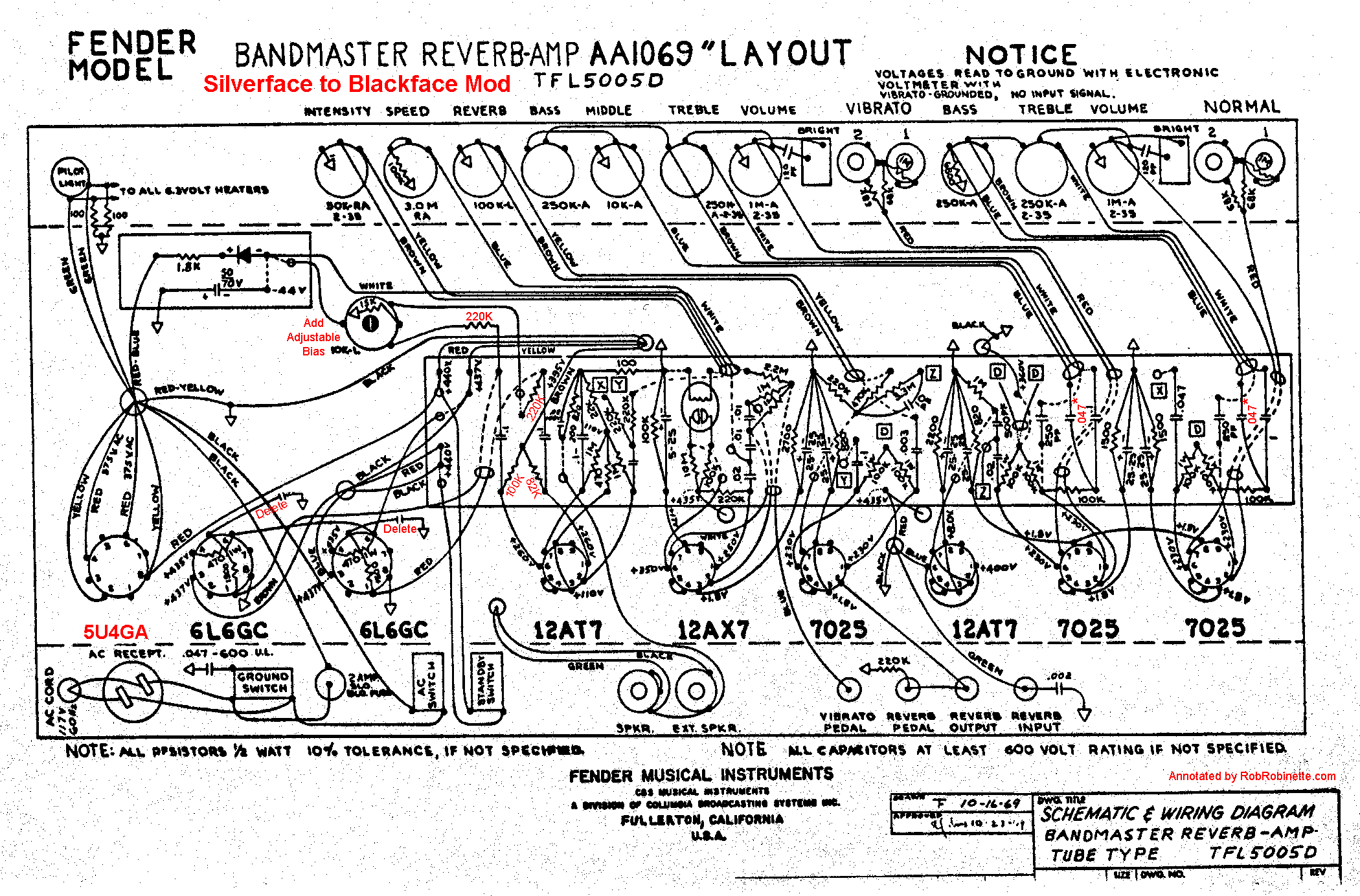
The AB763 Vibroverb came with an 8 ohm output transformer with 820 / 47 ohm negative feedback circuit. The Bandmaster Reverb uses a 4 ohm output transformer with 820 / 100 negative feedback circuit. The different NFB circuit compensates for the 4 ohm transformer's lower output voltage. As long as the Bandmaster Reverb is connected to a 4 ohm speaker load (typically two 8 ohm speakers) the outcome is the same.
All of the AB763 mods on this webpage apply to silverface amps that have been blackfaced.
Convert Bias Balance to Adjustable Bias + Bias Balance
This applies to silverface amps with a Bias Balance pot but no bias level pot. Simply replace the 15K resistor that's soldered to the original Bias Balance pot's back with a 10k 1/2 watt resistor and a 25k trim pot. The Balance pot still acts to balance the bias between the power tubes but the trim pot will adjust the bias level of all the power tubes. Turning the trim pot to reduce resistance will increase the bias current and make the bias hotter. Mod and photos by Rob Hull.
Original Silverface Bias Balance Circuit
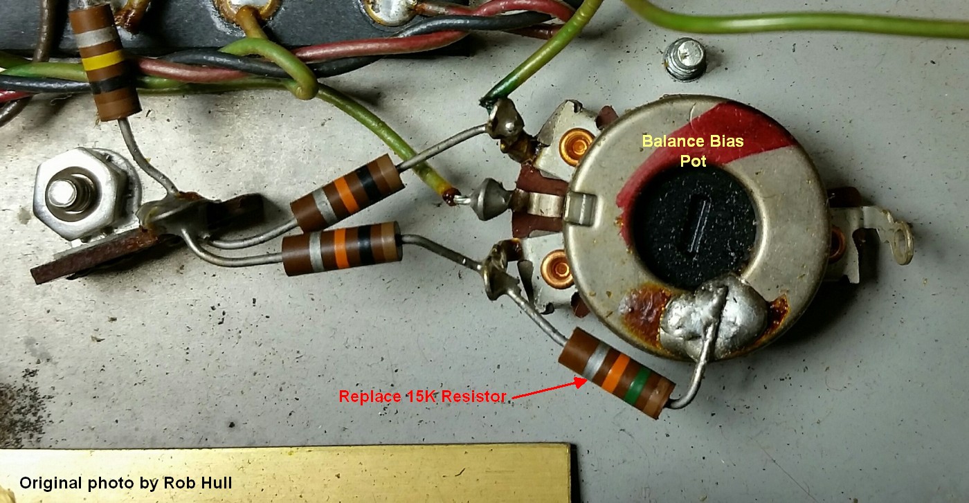
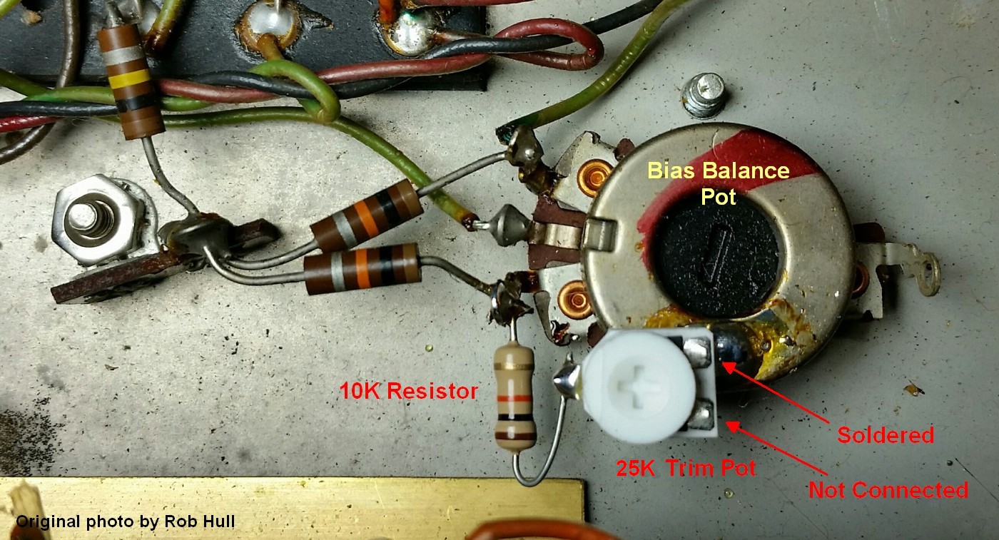
Replace the original 15k resistor with a 10k resistor + 25K trim pot. Set the trim pot to maximum resistance before installing so the bias will be set to coolest. You must bias the amp after this mod. The trim pot's upper right terminal is soldered to the back of the bias pot for a ground connection. The trim pot is wired as a variable resistor with the trim pot's lower right terminal not connected to anything.
Watch closely for power tube red plating when you start the amp up after this mod in case you set the Bias trim pot incorrectly. You will need to bias the amp after this mod. See this for info on biasing an amp.
AB763 With Tremolo Deleted
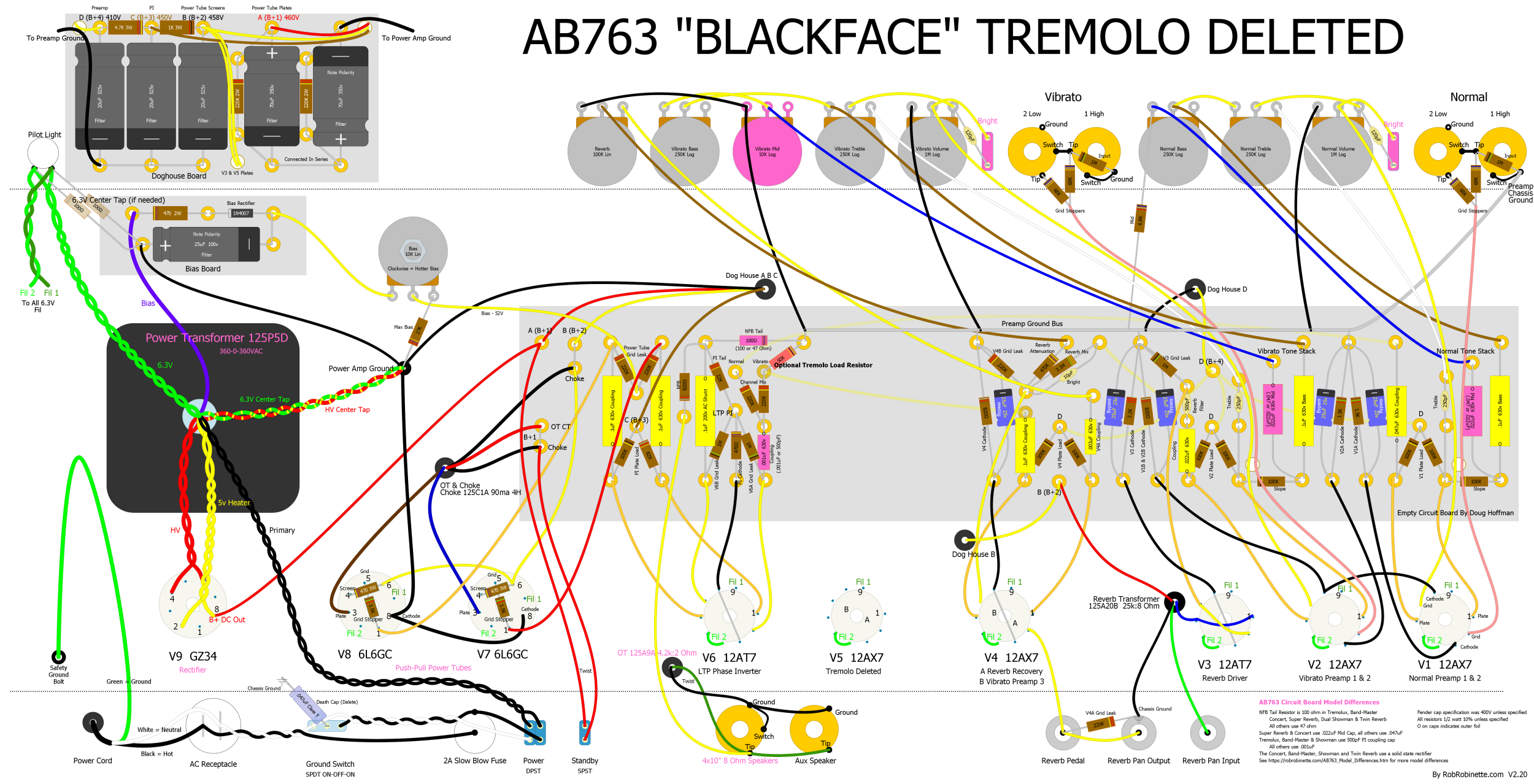
AB763 Vibroverb with reverb but tremolo has been deleted. V5 was used for tremolo so it is unused in this layout. Note the "Optional Tremolo Load Resistor" at center left of the circuit board. It applies the same circuit load as the tremolo to keep the Vibrato Channel's gain exactly the same as a normal AB763 blackface amp.
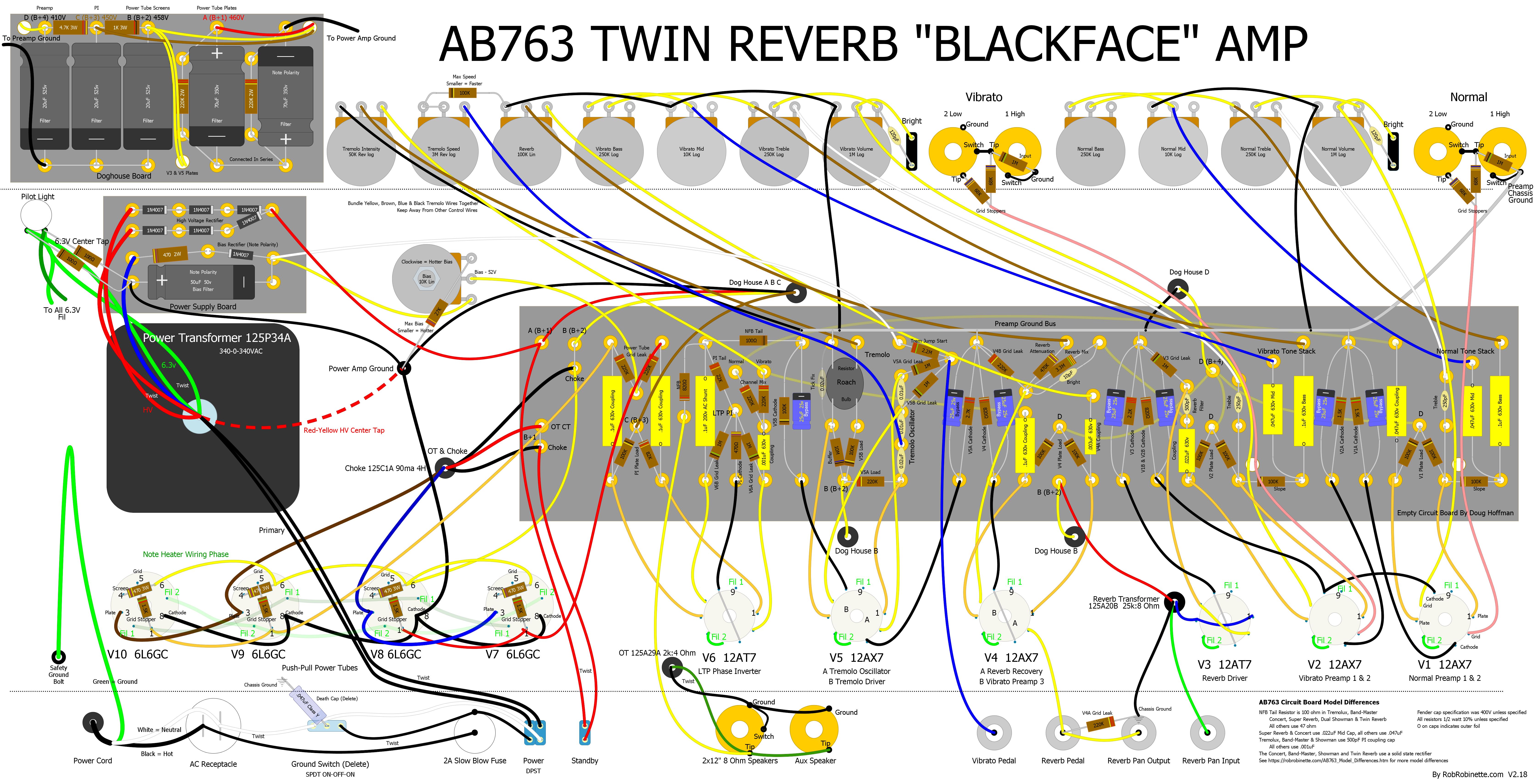
Click the image to see the hi-res version. The pdf is available here. The DIYLC file is available here.
AB763 Annotated Layout
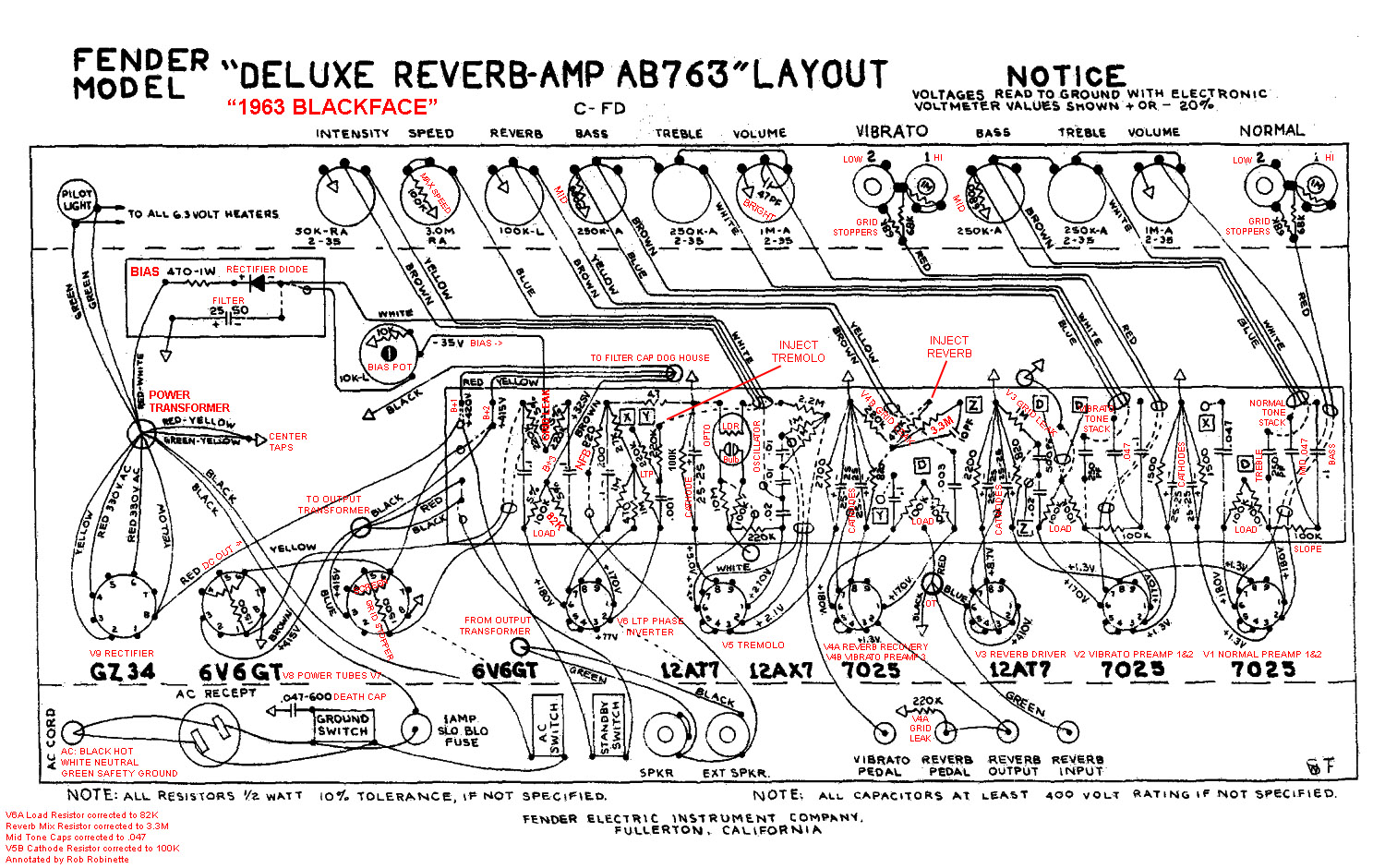
Click the image for the full size layout.
AB763 Twin Reverb Schematic
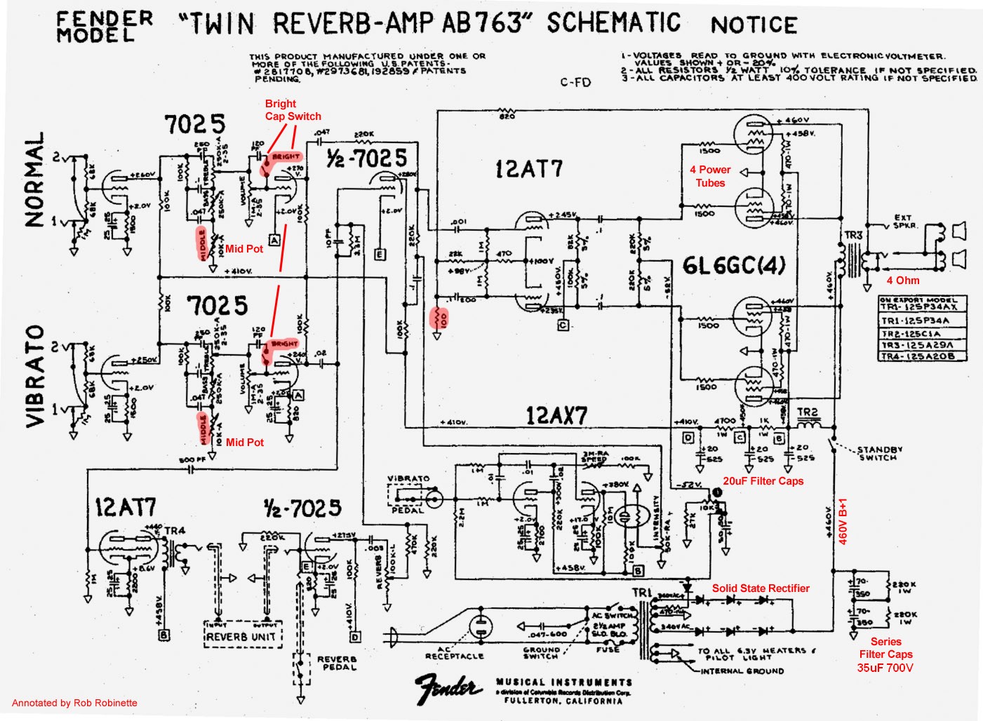
Some of the major differences between the Twin Reverb and Deluxe Reverb are highlighted.
AB763 Twin Reverb Layout

65 Deluxe Reverb Reissue Schematic
The 65 DRRI has the AB763 circuit on a PCB. Click the image for the full size schematic.
65 Deluxe Reverb Reissue PCB Layout
Click the image for the full size layout.
68 Custom Deluxe Reverb Schematic
The 68 CDR is not a silverface amp, it is an almost exact copy of the 64 Deluxe Reverb Reissue with just a few valuable tweaks. Click the image for the full size schematic.
68 Custom Deluxe Reverb PCB Layout
Click the image for the full size layout.
For more info on the AB763 circuit see How the AB763 Deluxe Reverb Works.
Have comments or corrections? Email rob at:
![]()
References
RCA Corporation, RCA Receiving Tube Manual, RC30.
Merlin Blencowe, Designing Tube Preamps for Guitar and Bass, 2nd Edition.
Merlin Blencowe, Designing High-Fidelity Tube Preamps
Morgan Jones, Valve Amplifiers, 4th Edition.
Richard Kuehnel, Circuit Analysis of a Legendary Tube Amplifier: The Fender Bassman 5F6-A, 3rd Edition.
Richard Kuehnel, Vacuum Tube Circuit Design: Guitar Amplifier Preamps, 2nd Edition.
Richard Kuehnel, Vacuum Tube Circuit Design: Guitar Amplifier Power Amps
Robert C. Megantz, Design and Construction of Tube Guitar Amplifiers
Neumann & Irving, Guitar Amplifier Overdrive, A Visual Tour It's fairly technical but it's the only book written specifically about guitar amplifier overdrive. It includes many graphs to help make the material easier to understand.
T.E. Rutt, Vacuum Tube Triode Nonlinearity as Part of The Electric Guitar Sound
By Rob Robinette
[ How the 5E3 Deluxe Works ] [ Deluxe Models ] [ My 5E3 Build ] [ The Trainwreck Pages ] [ Fender Input Jacks ] [ B9A Prototype Boards ]