How to Bias a Tube Amplifier
By Rob Robinette
WARNING: A tube amplifier chassis contains lethal high voltage--sometimes over 700 volts AC and 500 volts DC. If you have not been trained to work with high voltage then have an amp technician adjust the amp's bias. Never touch the grounded chassis with one hand while probing with the other because a lethal shock can run between your arms through your heart. Use just one hand when working on a powered amp. See more amplifier safety info here.
What is Bias?
Bias voltage is the voltage difference between a tube's cathode and control grid. Bias current is the amount of electrons flowing from the cathode to the plate with no audio signal on the control grid (idle current). An amplifier tube controls the flow of electrons running through it. The tube can stop the flow completely (called cutoff) or let it flow at maximum (called saturation). To amplify an alternating current (AC) guitar audio signal we need to set the tube's idle, or no-signal electron flow at a point to keep from overheating the tube's plate. We normally want to set the idle flow right in the middle between cutoff and saturation so there's equal room for both the positive and negative voltage of the guitar signal. When the guitar signal is a negative voltage it makes the control grid negative which repels the negatively charged electrons flowing through the tube which slows the flow. When the guitar signal is a positive voltage (positive voltage=scarcity of electrons) the grid goes less negative so there are fewer electrons on the grid to repel the flow so the flow through the tube increases.
Tube manufacturers list the tube's max bias in the tube datasheet as maximum plate dissipation given in watts. Remember watts = volts x amps. Plate dissipation is equal to the plate-to-cathode voltage x plate current. The higher the plate voltage the lower the plate current must be to stay under the plate dissipation limit.
We adjust the voltage difference between the cathode and control grid (bias voltage) to adjust the amount of electrons flowing from the cathode to the plate. In fixed bias amps we adjust the grid voltage to set the bias. In cathode biased amps we must change the cathode resistor value to change the cathode voltage to adjust the bias.
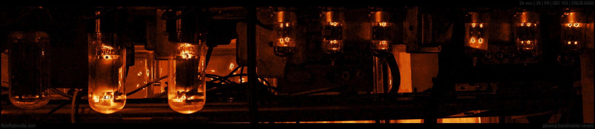
If you bias an amp too hot the power tubes can "red plate." The plates glow red hot from too many electrons pounding the metal plates.
Note that the maximum plate dissipation current does not equal the saturation current (wide open current flow). With the plate dissipation (a heat limit) set at 100% the tube can still flow more electrons so the saturation current is greater than the max plate dissipation current. When an AC guitar signal is applied to the power tube grid the tube's current flow will fluctuate above and below the idle current. As long as the average current flow does not exceed the max plate dissipation the tube operation is safe. Saturation is an absolute current limit (the tube is wide open) but max dissipation is an average heat limit.
Right Power Tube Red Plating
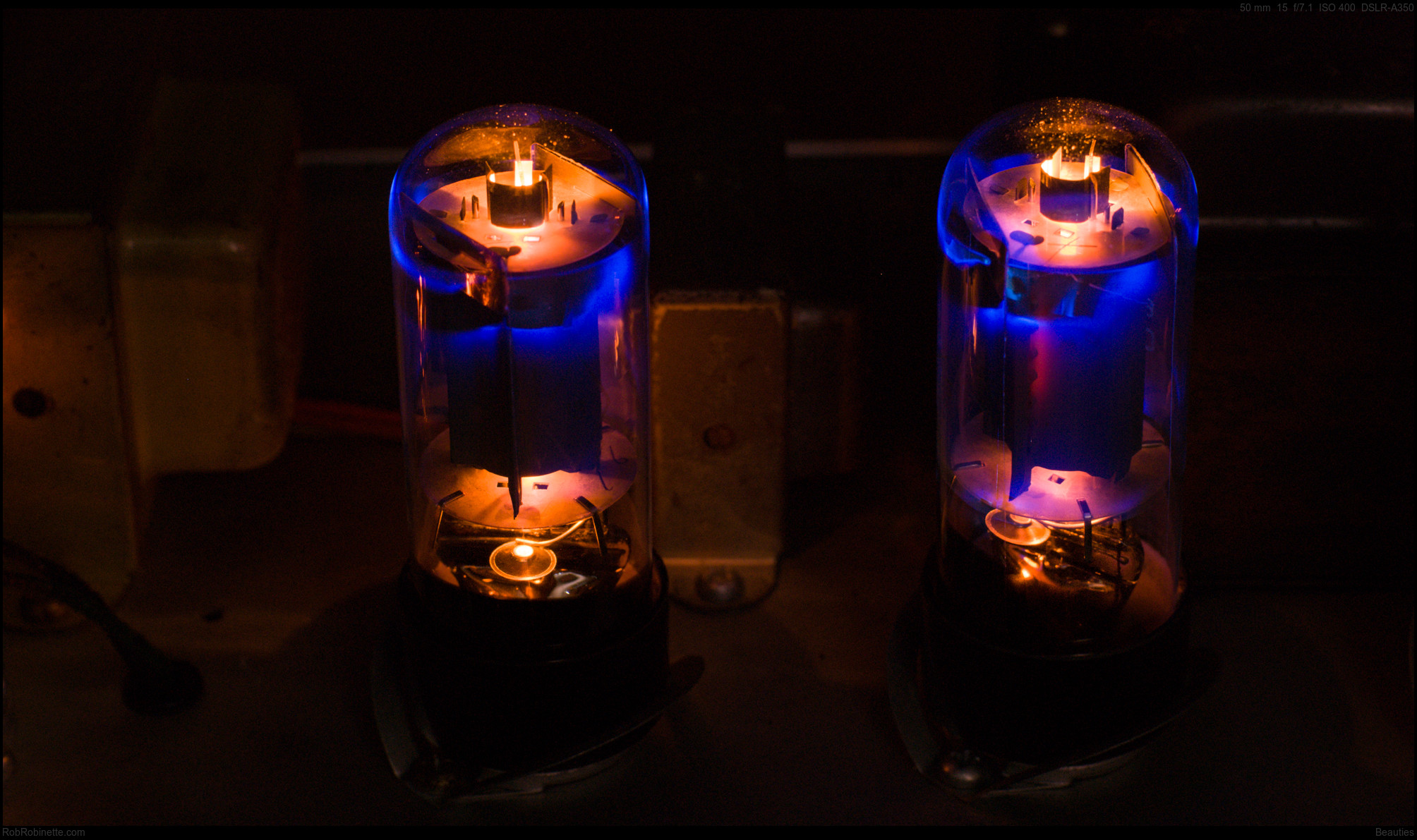
The red plating is caused by too much heat from too many electrons pounding the plate. The cool blue glow is caused by electrons colliding with gas molecules.
Measure Bias With the Output Transformer Resistance Method
This is my recommended method of measuring plate current and bias for both fixed bias and cathode bias amps. The quiescent (idle or no signal) plate current can be calculated by measuring the output transformer's resistance and voltage drop between the output transformer's center tap and both power tube plates. This transformer resistance method is just as accurate if not more so than directly measuring the current using the "output transformer shunt method" (detailed in the next section) and this method is much safer.
Measurement Overview
1. With a powered and warm amp, measure the output transformer center tap voltage and both power tube plate voltages (usually pin 3).
2. Subtract the plate voltage from the center tap voltage to get the output transformer voltage drops for both tubes.
3. Turn off the amp and measure the resistance in ohms from the center tap to the power tube plates.
4. Divide the voltage drop by the resistance to get the bias current.
Measure and record the plate voltage, voltage drop between the center tap & both power tube plates and the resistance between the center tap & both plates. You only have to measure the resistance once for the life of the transformer.
1. The first step is with the amp off and unplugged, clip the multimeter ground probe to a good ground. I recommend using the power transformer center tap ground connection. Doing this will allow you to use only one hand to safely take high voltage measurements.
With the ground probe clipped on, turn on the amp (standby switch too) and let it warm up with the volume full down for a few minutes. When warm, measure and record the plate DC voltage on both of the power tubes (usually pin 3). The tube plates will be connected to the output transformer. This will be high voltage DC at 300 to 600 volts. Record the voltage to all the decimal places displayed by your meter--the more accurate the better (if you are using a Fluke 87 meter hold the light bulb button down for 1 second to enter the high resolution mode). Do not allow the multimeter probe to make contact with the adjacent socket pins.
Octal Tube Socket Numbers
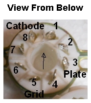
Plate is pin 3 and Cathode is pin 8. Arrow points to the insertion index notch.
2. Next we measure the output transformer voltage at the center tap. The standby switch may be directly connected to the center tap so you may be able to measure its voltage there at either standby switch terminal. Record the center tap voltage then subtract the plate voltage from the center tap voltage to get the voltage drop. This is the voltage drop through half the transformer. You can also measure the voltage drop directly by putting your meter probes on the plate pin and center tap but this is much more dangerous.
Bias Points in the 5E3 Deluxe
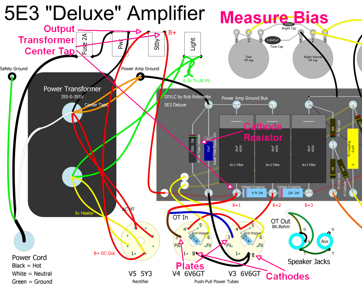
On many amps the output transformer center tap can be accessed at either terminal of the Standby Switch or where the output transformer center tap lead is connected to the circuit board. Note the power tube plates (pin 3) and the power tube Cathode Resistor.
3. Turn the amp off, unplug it and ensure the filter capacitors are discharged then measure the output transformer resistance between the output transformer center tap and both tube plates. You want to do this with the output transformer still warm to get the most accurate reading. Record the resistance to as many decimal places as your meter shows. You only have to measure the transformer resistance once for the life of the transformer so write down the resistance and use it for all future bias setting sessions.
4. Next we divide the voltage drop by the ohm reading to get the plate current in amps.
Example: When I measured these values on my 5E3 Deluxe I got:
Tube V3: 1.347 volt drop and 72.0 ohms between the standby switch (center tap) and tube plate = 1.347 / 72.0 = .0187 amps or 18.7 milliamps
Tube V4: 1.325 volt drop and 80.7 ohms = 1.325 / 80.7 = .0164 amps or 16.4 milliamps
I used my Fluke 87 multimeter to compare this bias measurement method with directly measuring the bias current using the "transformer shunt method" (described below in next section) and got results within 1 milliamp.
With the plate voltage and milliamp values go to my Tube Bias Calculator. Select your tube type, enter the plate voltage and click a Calculate button.
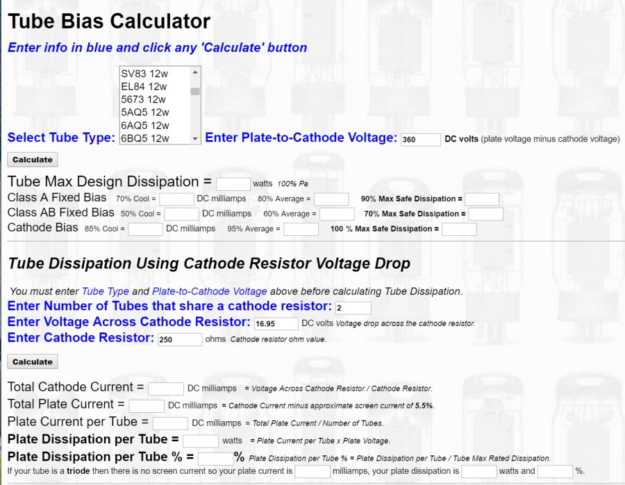
Screen capture of the Tube Bias Calculator webpage.
For Class AB Fixed Bias amps (push-pull) 70% of max dissipation at idle is your safe limit.
For Class A Fixed Bias amps (single ended) 90% of max dissipation is your safe limit.
For All Cathode Biased amps 100% of max dissipation is your safe limit.
Go down to the calculator's Tube Dissipation Using Plate Current section and plug in your plate current milliamp values and hit any Calculate button to see what % of max dissipation you are running. I usually set my push-pull amps around 70% unless a lower setting sounds better--yes play your amp after every bias change as you may find you prefer a cooler bias setting. Fender tended to bias their push-pull amps cool from the factory at around 50 to 60%.
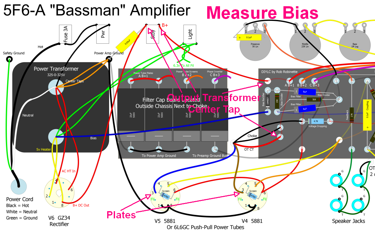
In the 5F6A Bassman the output transformer center tap can be accessed at either terminal of the Standby Switch or where the output transformer center tap lead is connected to the circuit board. Note the power tube plates (pin 3). This Bassman amp has fixed bias so it does not have a power tube Cathode Resistor.
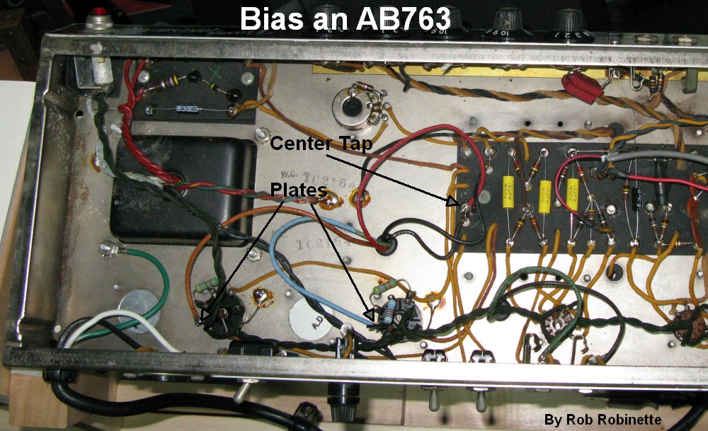
Fixed bias AB763 blackface bias measurement points.
To Calculate the Bias Manually
Get the tube maximum Plate Dissipation in watts from the power tube datasheet (Google search: 6V6 datasheet)
The 6V6 is rated for 12 watts, JJ 6V6 is 14 watts, 6L6GC is 30 watts.
Plate Dissipation in watts = Plate Voltage * Plate Current
The Plate Current must be in amps, not milliamps so if you get 19.4 milliamps convert that to .0194 amps by dividing by 1000. For cathode biased amps use plate-to-cathode voltage, not plate voltage. To measure plate-to-cathode voltage place one meter probe on the plate pin 3 and the other probe on the cathode pin 8.
Plate Dissipation % = Plate Dissipation / Tube Maximum Plate Dissipation
Example: Your 6V6 is rated for 12 watts max, you measure 400 volts of plate voltage and 19.4 milliamps of plate current.
Plate Dissipation = 400v * .0194a = 7.76 watts of Plate Dissipation
Plate Dissipation % = 7.76w / 12w = .65 or 65%
Adjusting the Bias
If your amp has fixed bias with a bias pot make small changes when adjusting the bias pot and measure the plate voltage and plate current again. You have to measure the voltage each time because the voltage and current will change with a bias pot change. As you turn up the bias and flow more current through the power tube the demand on the power transformer and rectifier will cause the plate voltage to drop. Calculate the bias % after each bias pot adjustment and sample the amp's clean and overdrive tone.
If your amp has fixed bias without a bias pot (like the original 5F6A Bassman) you must either install a bias pot or replace bias resistors to adjust the bias.
If your amplifier is cathode biased you must replace the cathode resistor to change the bias level. A higher value cathode resistor will cool the bias, a lower value will warm the bias. Cathode biased amps can safely run at 100% plate dissipation at idle.
If your amplifier has bias tremolo you need to sample the tremolo after you adjust the bias. Too hot of a bias can give you a weak tremolo.
Setting a higher % of max dissipation will make the bias 'hotter.' The power tube grid voltage is always negative on fixed bias amps and a hotter bias will have the grid voltage closer to zero. A hot bias for a 5F6A Bassman would be around -44V DC. Setting a lower % of max dissipation will make the bias 'cooler' and the grid voltage will be a larger negative number like -50V.
For my Tung-Sol 5881 power tubes rated at 26 watts of max dissipation in my 5F6A Bassman I ended up with 448v on the plates and 40.0 milliamps of plate current which equals 69% of max dissipation with 70% (40.6ma) being the max safe dissipation for fixed bias Class AB amps. The grid voltage was -45.1V DC (yes, a negative voltage). When running a 5Y3 rectifier and 6V6GT power tubes the plate voltage was 367v with 18.7 milliamps of plate current for 6.9w of dissipation (max is 12w) for 57.2% of max.
Bias Differences Between Power Tubes
There will almost always be a difference in bias between power tubes. The difference can be caused by the tubes or the surrounding circuit.
To minimize the difference between the power tubes first measure each power tube's bias.
Then swap the power tubes between their sockets and again check the bias of each tube.
If the difference between the two tubes is smaller, which is desirable, leave them in place. If the bias difference is larger swap them back.
Don't worry too much about a bias imbalance because it can actually improve the amp's tone by adding even order harmonic distortion. Using matched power tubes is not important in guitar amps.
Measure the Bias by Cathode Resistor Voltage Drop
If your amp is cathode biased or has 1 ohm bias setting cathode resistors then you can calculate bias current by measuring voltage drop across the cathode resistor. To do this set your multimeter for DC Volt measurement, clip the black probe to a chassis ground (so you can use just one hand to do the measurement) and put the red probe on the tube socket cathode pin 8. You can also put one probe on each leg of the cathode resistor. The voltage shown on the meter is the 'voltage drop' (disregard any minus sign).
Note the Cathode Resistor at center and the power tube plates and cathodes at bottom center.
Measure the Plate-to-Cathode Voltage by placing one meter probe on the plate pin 3 and the other probe on the cathode pin 8.
Once you have the voltage drop across the cathode resistor and Plate-to-Cathode Voltage recorded go to my Bias Calculator and enter your Tube Type and Plate-to-Cathode Voltage at the top of the page, then go down to the Tube Dissipation Using Cathode Resistor Voltage Drop section and enter the Number of Tubes that share a cathode resistor, the measured Voltage Drop across the cathode resistor and the Cathode Resistor's Ohm Value and click Calculate.
The Bias Calculator webpage assumes 5.5% of the current flowing through the cathode resistor is screen current so it is subtracted out to give you a more accurate plate current.
You can get a more accurate bias measurement if you measure the resistance of your cathode resistor. It may be marked as a 250 ohm resistor but actually measure 238. To measure the cathode resistor turn the amp off and measure the resistance from the tube cathode pin 8 to ground.
Measure Bias With the Output Transformer Shunt Method
Another method used to measure bias is the output transformer shunt method. This method has you directly measure the power tube plate current but it is much more dangerous than the previous method for reasons you'll see below. Another reason to avoid this method is typically milliamp measurement is less accurate than volts and ohms for most multimeters.
The first step is to measure and record the plate DC voltage on both of the power tubes' plate (pin 3). The plate pin usually has a blue or brown wire coming from the output transformer. The voltage should usually be between 300v to 500v DC.
Then set your multimeter to measure DC milliamps. Normally this involves moving the meter's red probe to another meter socket. Some meters require you to push a button to set DC or AC, make sure you're measuring DC current. If you have two multimeters use the best one to measure DC current and the other to measure DC voltage so you don't have to go back and forth on one meter. If you do use one meter don't forget to switch the meter probes and settings as you go back and forth between measuring DC current and DC voltage.
WARNING: When measuring milliamps (current) as soon as either meter probe makes contact with a voltage that same voltage passes through the meter to the other probe--both meter probes will be hot with high voltage so you must control both probes carefully. You must wear safety glasses because if a meter probe accidentally contacts a grounded component an arc will occur and molten metal will spray out from the arc. This procedure is dangerous and if you are not trained for working with high voltage I recommend you take your amp to a professional tech.
Place one probe on either power tube's plate (pin 3). The other meter probe now has high voltage DC on it so be careful as you place it on the output transformer center tap. In many amps the standby switch is connected directly to the output transformer's center tap so you can use either standby switch terminal as the output transformer center tap. Refer to your amp's schematic and layout diagrams to find a place to sample the output transformer's center tap. With your meter contacts on a plate pin and output transformer center tap read the plate current in milliamps. Carefully do the same for the other power tube's plate (pin 3). Be careful not to make contact with anything as you remove both meter probes from the amp chassis.
Bias Points in the 5F6A Bassman
Output transformer center tap points at center and power tube plates at bottom center.
With the plate voltage and milliamp values go to my Tube Bias Calculator. Select your tube type, enter the plate voltage and click a Calculate button. The 5F6A is a Class AB Fixed Bias amp so 70% of max dissipation is your safe limit. Go down to the Tube Dissipation Using Plate Current section and plug in your plate current milliamp values and hit any Calculate button to see what % of max dissipation you are running.
References
RCA Corporation, RCA Receiving Tube Manual, RC30.
Merlin Blencowe, Designing Tube Preamps for Guitar and Bass, 2nd Edition.
Merlin Blencowe, Designing High-Fidelity Tube Preamps
Morgan Jones, Valve Amplifiers, 4th Edition.
Richard Kuehnel, Circuit Analysis of a Legendary Tube Amplifier: The Fender Bassman 5F6-A, 3rd Edition.
Richard Kuehnel, Vacuum Tube Circuit Design: Guitar Amplifier Preamps, 2nd Edition.
Richard Kuehnel, Vacuum Tube Circuit Design: Guitar Amplifier Power Amps
Robert C. Megantz, Design and Construction of Tube Guitar Amplifiers
Neumann & Irving, Guitar Amplifier Overdrive, A Visual Tour It's fairly technical but it's the only book written specifically about guitar amplifier overdrive. It includes many graphs to help make the material easier to understand.
T.E. Rutt, Vacuum Tube Triode Nonlinearity as Part of The Electric Guitar Sound
[ How the 5E3 Deluxe Works ] [ Deluxe Models ] [ DRRI & 68 CDR Mods ] [ Amp Troubleshooting ] [ My 5E3 Build ] [ Spice Analysis ] [ The Trainwreck Pages ] [ Fender Input Jacks ] [ B9A Prototype Boards ]