JCM800 6V6 & Micro Guitar Tube Amps
By Rob Robinette
Have comments or corrections? Email rob at: robinette at comcast dot net
UPDATE April 2026: Added a Quad EF80 power amp version of the JCM800 Micro.
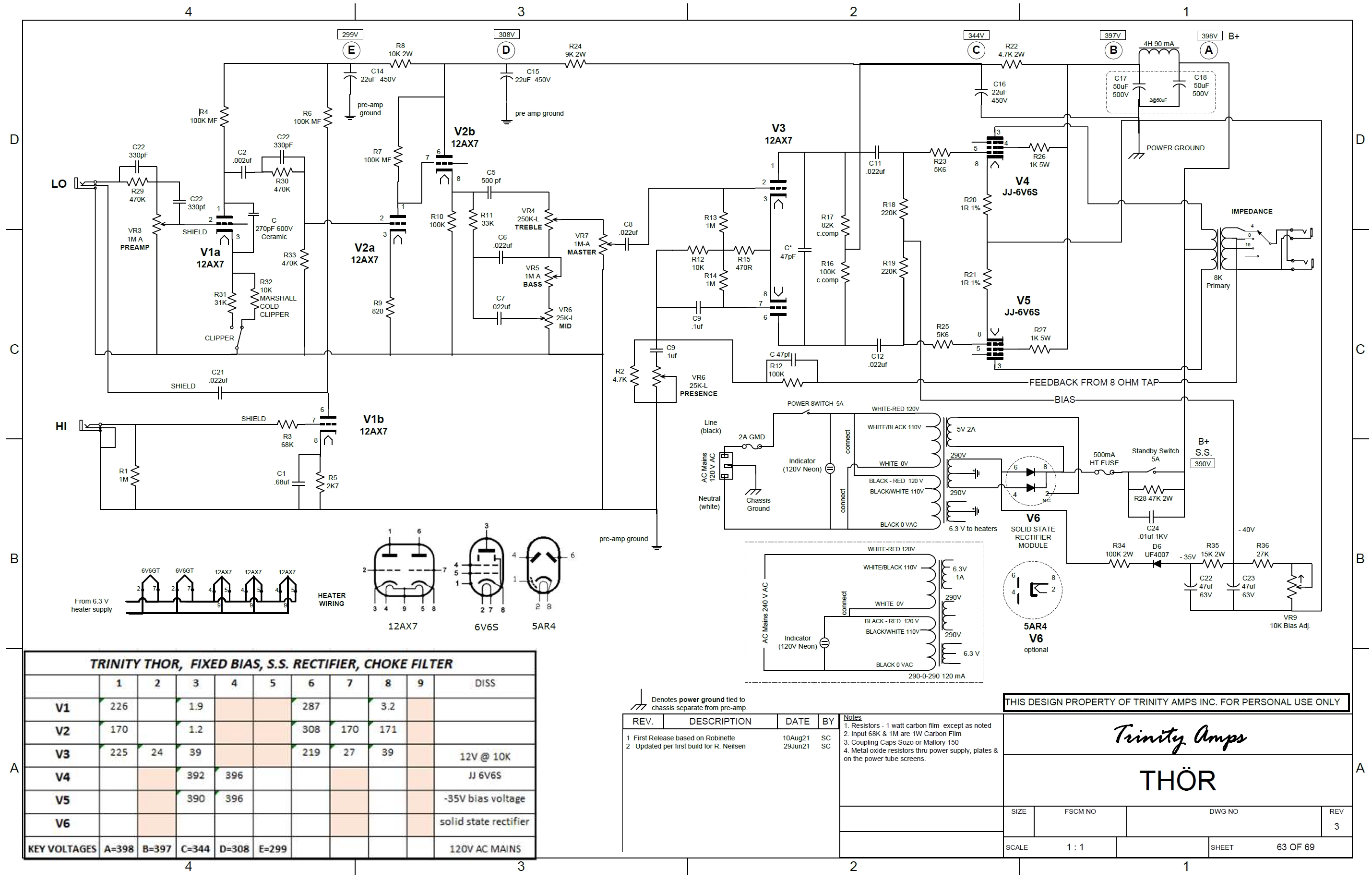
UPDATE April 2022: Trinity Amps is selling the JCM800 6V6 in either kit form or a fully built combo or head amp. They are calling it the Thör. It's a variation of their Trinity 18 Amp. Here's their webpage. Scroll down to the Thör section.
From the Trinity Amps website:
The Trinity Amps Thör is a 6V6 powered amp authentic to the Marshall JCM800 2203 Lead Series Master Volume amp, based on original work by RobRobinette.com and it totally delivers. In addition to the Lo Sensitivity input, Thör employs a cascaded Hi Sensitivity channel. With a pre-phase inverter master volume and a cold biased “cold clipper” gain stage and the circuit tweaked to deliver an aggressive but sweet overdrive tone, Thör has the quintessential Marshall tone and crunch but in a very usable 20 watt package. The Preamp, tone stack and Phase Inverter are identically voiced to the JCM800 2203. There is some frequency compensation employed to retain the 2203 circuit and smooth it out.Running an octal socket based solid state rectifier with choke, the 400V fixed-bias supply powers two JJ 6V6Ss. There is an added Clipper switch to select either JCM cold clipper or the SLO cold clipper. The gold, brushed aluminum look front panel is intentionally reminiscent of the original JCM800s. Available as a Head or Combo. Get the Classic Marshall tone you’ve heard over a zillion times! Be sure to watch the videos below. Thor is the god of thunder, lightning, storms and strength. A classic name for this powerful sounding Trinity Amps product.
UPDATE January 2021: I added an EF80 small pentode version of the JCM800 Micro.
UPDATE August 2020: In version 3.1 I corrected an error I made in the JCM800 6V6 design. I spec'd a 56K NFB resistor when 100k is what is needed. We get less NFB signal from the 6V6 power amp but we get more by going from the JCM800 4 ohm secondary to the 6V6's 8 ohm secondary so 100k is what we need. I also changed the JCM800 6V6 and Micro preamp and master volume type to match the JCM800. The preamp tweaks and post phase inverter master volume were not the improvements I thought they would be. I decided it was better to offer up a "stock" JCM800 and let builders tweak that design to their preferences.
Design Philosophy
The Marshall 2104 Master Volume/JCM800 is my favorite high gain amp of all time. It is the sound of 80's rock-and-roll guitar but it's just too loud at 50 or 100 watts. These 20 watt 6V6, 2 and 4 watt EF80, and 1 watt 12AU7 amps will allow you to shred at less than ear splitting volume and lay down studio licks without ear plugs. The preamp is all 2104/JCM800 but the power amp consists of the stock long tail pair phase inverter feeding either a pair of 6V6, two two EF80, 4 EF80 or a single 12AU7 power tube in true push-pull. The layouts are designed for use in a standard Princeton Reverb chassis and cab which allows the use of a 10 or 12 inch speaker. Many people gig with Princeton Reverbs so here's a shredding machine in a Princeton Reverb package.
Tweaking the Overdrive Intensity & Tone
JCM800 Micro EF80 Pentode 2 Watt
JCM800 Micro EF80 Quad Pentode 4 Watt
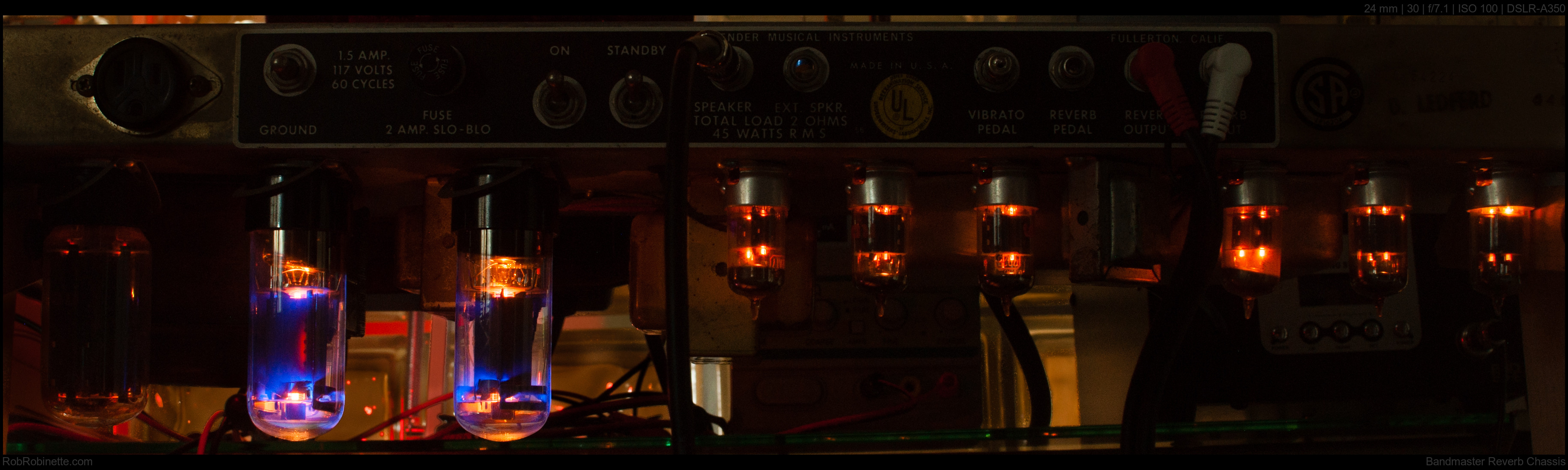
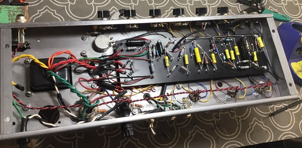
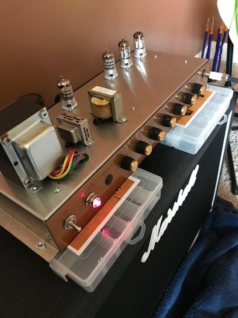
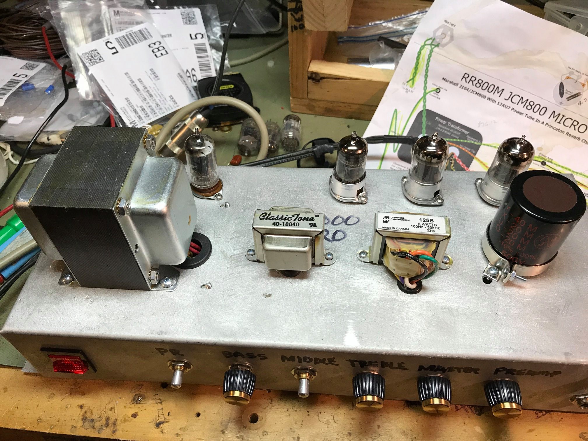
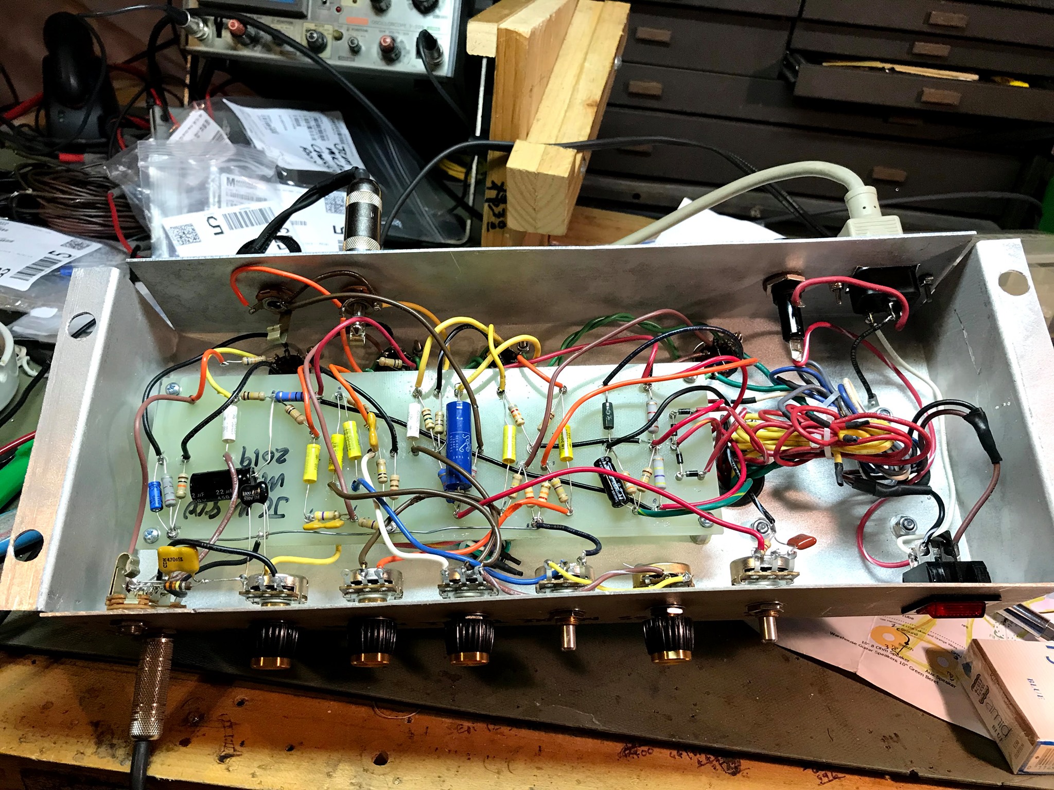
Marcus Albrecht's JCM800 6V6
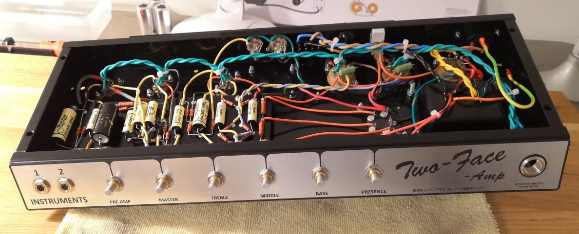
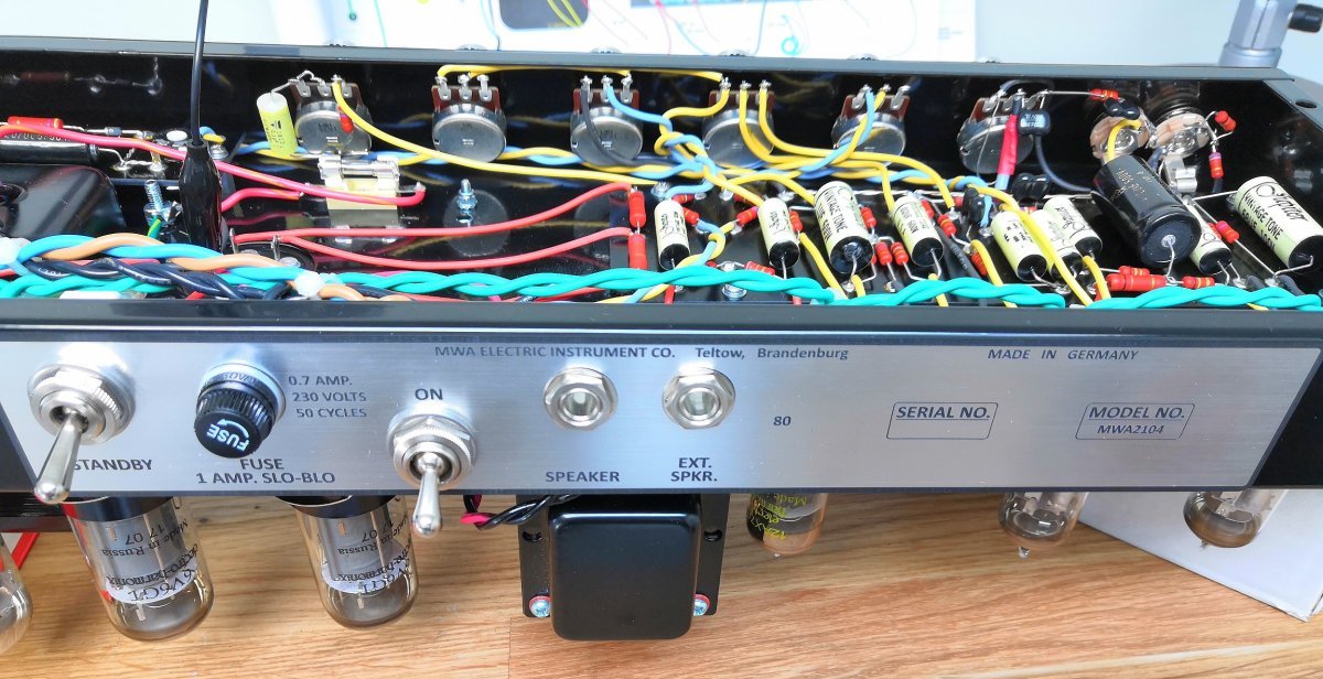
Marcus used a tube rectifier. Photos by Marcus Albrecht.
JCM800 6V6
The JCM800 6V6 comes in a Princeton Reverb size package but it can run 6V6, 5881, 6L6 and EL34 power tubes for 22 to 25 watts of output. I spec the AllenAmps.com TP25 power transformer and TO26 output transformer which support 6V6, 5881, 6L6 and EL34 power tubes. Both of these transformers are Princeton Reverb upgrade transformers with a lot more oomph than stock transformers. They fit perfectly in the Princeton Reverb chassis. Although I prefer the Allen Amps transformers, any Princeton Reverb power and output transformer and choke can be used if you plan to use only 6V6 power tubes.
The preferred choke is the Classictone 40-18032 5H 120ma but again, any Princeton Reverb or Deluxe Reverb choke can be used. The bias circuit uses the power transformer's 50v tap and features bias balance and bias adjustment for 6V6, 6L6 and EL34 tubes. If you use a power transformer that does not include a 50 volt bias tap you can use this circuit to generate bias voltage from the power transformer high voltage tap. The power tube sockets are wired for EL34 compatibility.
Power output will be around 22 watts with 6V6 power tubes and somewhere around 25 watts with 6L6 and EL34 power tubes. Output is limited due to output transformer saturation. A pair of 23 watt 5881 power tubes is also a great match for this amp. We compensate for the different power tube plate load requirements by adjusting speaker load. For 6V6 power tubes we use an 8 ohm speaker with the 8 ohm speaker jack. For 6L6, 5881 and EL34 power tubes we connect the 8 ohm speaker to the 16 ohm speaker jack. The TO26 output transformer has both 8 and 16 ohm speaker outputs and I connect each to a separate speaker jack to make switching between tube types easy. Note that neither speaker jack has a shorting switch so always make sure a speaker is connected before powering up the amp. Also note the NFB is tapped off the 8 ohm speaker jack.
If you don't need the 6L6/EL34 option then standard Princeton Reverb power and output transformers will work fine.
JCM800 6V6

Click the schematic to see the high resolution image. Download the pdf and DIYLC file.

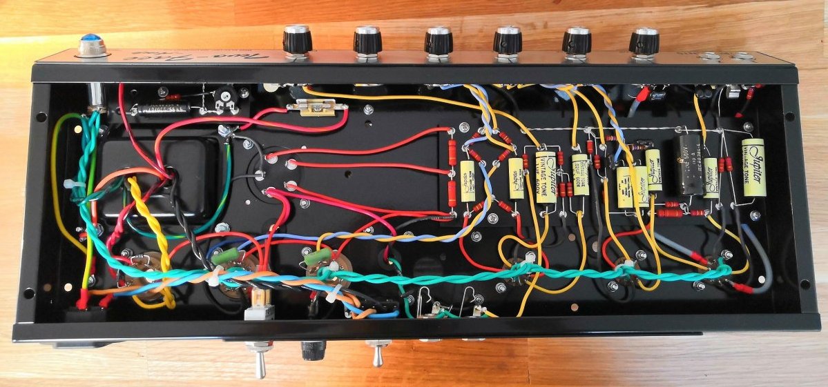
JCM800 in a Princeton Reverb chassis. The preamp ground bus is grounded at the High Input jack ground terminal. The layout is an accurate depiction of a Princeton Reverb chassis. Note that neither speaker jack has a shorting switch. Click the layout to see the high resolution image. Download the pdf, DIYLC and Hoffman circuit board DIYLC file.
The cap can is a JJ 40/20/20/20uF 500v can from Mojotone.com. The can's terminals are marked with Y, X, U, O and "-" stamped in the terminals. The Y terminal is 40uF and the X, U and O have 20uF. The "-" is the negative or ground terminal.
You can use a standard Princeton Reverb size cab with either a 10" or 12" speaker. Mojotone sells a nice Princeton Reverb head cab too.
Circuit Tweaks
The NFB resistor is kept at 100k because this amp's 8 ohm secondary puts out 41% higher voltage than the original JCM800's 4 ohm secondary but this is offset by the lower output of the 6V6 power tubes.
A JJ Princeton Reverb 40/20/20/20uF 500v cap can is used for B+1 through B+4 and a 22uF 500v cap is placed on the circuit board for B+5.
The 0.68uF V1A cathode bypass cap does not need to be an electrolytic. Any type of cap will work fine. I'm a fan of tantalum caps for .47uF and .68uF bypass caps. The bypass cap should be rated at 10 volts or higher.
The 6.3v heater center tap is elevated by connecting it to a Bleeder/Divider circuit at 65 volts. This heater elevation makes life much easier on the cathode follower and reduces heater hum (see layout above). If your power transformer does not have a 6.3v heater center tap then connect an artificial center tap (two 100 ohm 1/2 watt resistors) to the Bleeder/Divider circuit.
You can upload the JCM800 6V6 Hoffman circuit board DIYLC file to Hoffmanamps.com and Doug will make an eyelet or turret board for you. The empty board with eyelets or turrets installed is $20 + shipping. I used to make my own turret boards but with HoffmanAmps.com accepting DIYLC files to make custom boards it's just too easy and inexpensive to bother with making them myself.
Be sure and turn the Bias Balance pot to mid turn and set the Bias trim pot full cold (full counter-clockwise) before setting the power tube bias for the first time.
If your amp has stability and oscillation issues try chopsticking the amp leads around. Try to separate the preamp plate and grid wires as much as you can. If you still have stability and oscillation issues, placing a 270pF to 1000pF (.001uF) 600v+ ceramic disc cap across V1A (first preamp stage) pins 1 & 3 (plate & cathode) will help. This stability disc cap is present in many factory Master Volume/JCM800 amps. The cap's purpose is to remove above-human-hearing high frequencies which reduces the probability of the amp going into oscillation.
If you are concerned about cathode follower grid-to-cathode arcing at startup you can connect this 120v neon bulb between V2B (cathode follower) pins 7 & 8 (grid and cathode). You can also use a 10k 1/2 watt resistor in series with a 1N4007 diode instead of the bulb. Connect the diode stripe (cathode) to pin 8 (cathode). If you start blowing V2 tubes then this is the fix you need.
Speaker Suggestions
An 8 ohm speaker load (1x8 ohm or 2x16 ohm in parallel) is preferred because it makes it easy to switch between 6V6 and 6L6/EL34 tubes. For 6V6 tubes connect the 8 ohm speaker to the 8 ohm speaker jack. For 6L6, 5881 or EL34 tubes connect the 8 ohm speaker to the 16 ohm speaker jack. Doing this adjusts the power tube plate load for optimum load (7k ohms for 6V6 and 3.5K for 6L6, 5881 and EL34).
My favorite Celestion speaker for this amp is the Celestion G10 Vintage (60 watts) but I actually prefer the Warehouse Guitar Speakers ET10 (65 watts) speaker. If you go with two speakers then the Green Beret in 10 (25 watts) or 12 inch (25 watts) works really well. I prefer 10 inch speakers for Princeton Reverb combo cabs.
If you want a 12" speaker in a Princeton Reverb combo cab consider enlarging the cab. Adding two inches to the cab's height or width will allow a 12 inch speaker to breathe and not sound so boxy. Most cab makers will customize their cabs if you ask. If you use a single speaker it needs to be rated for about 40 watts. My top recommendation for a single 12 inch speaker is the Warehouse Guitar Speakers ET65 (65 watts). The Celestion Classic Lead (80 watts) for high gain lead style play is also a good speaker choice.
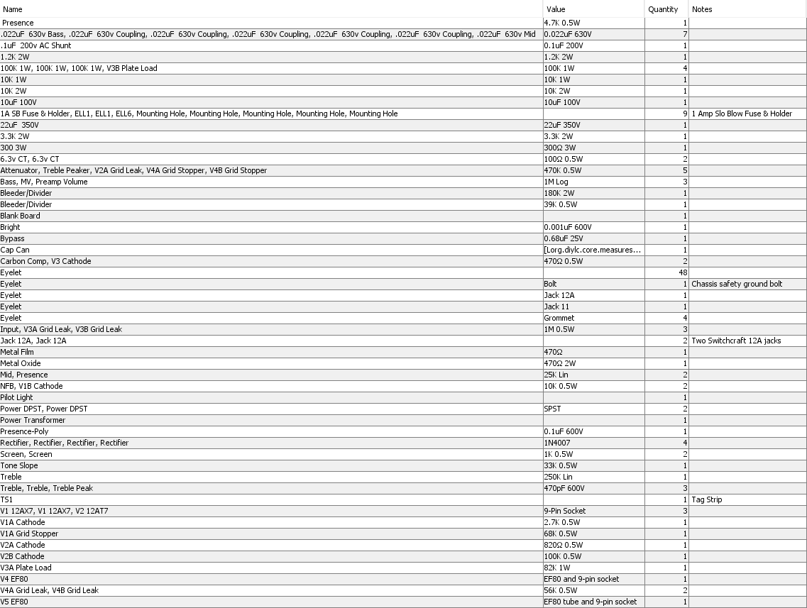
JCM800 6V6 Bill of Materials
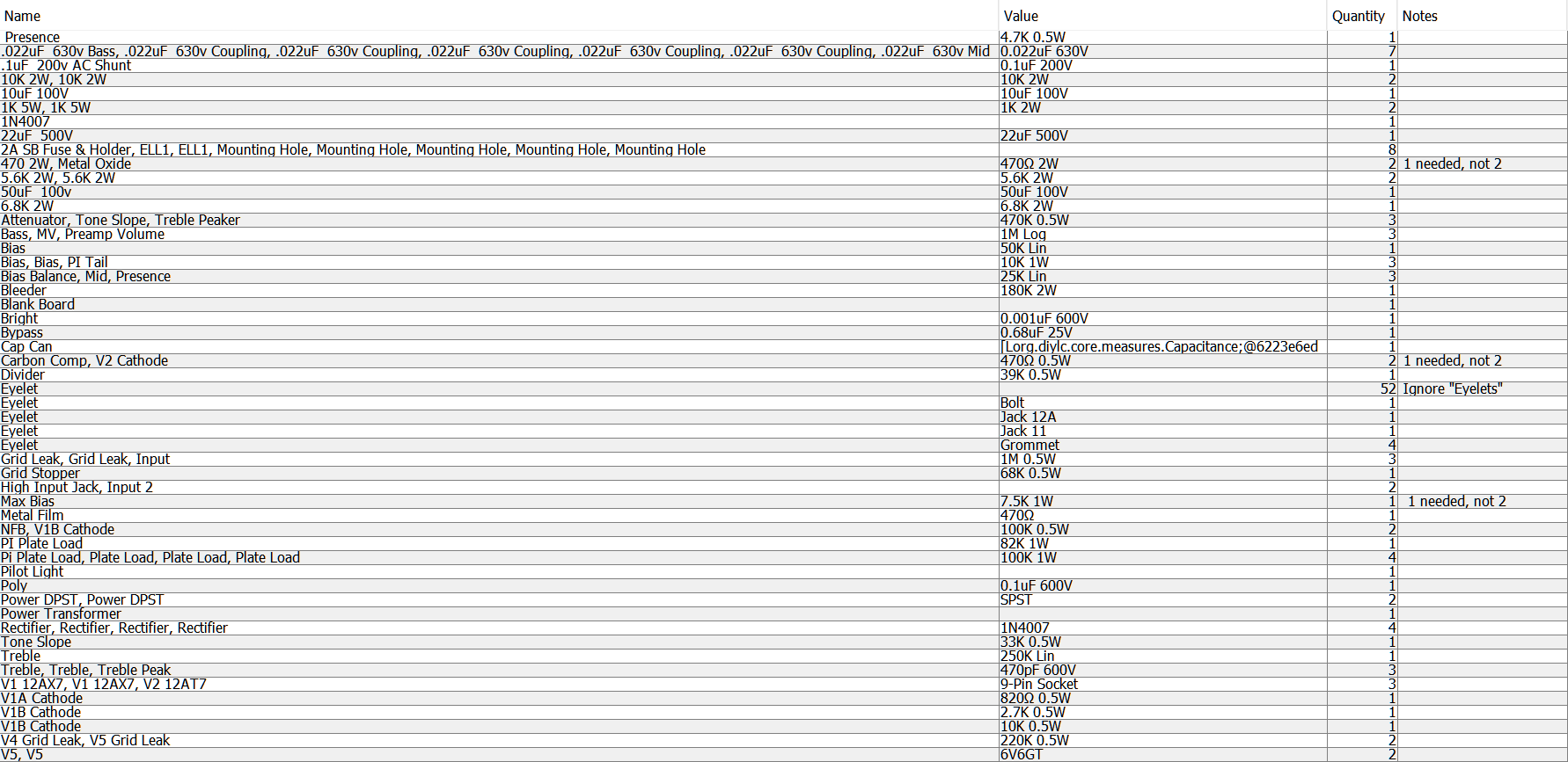
You'll also need a chassis, cab, speaker, power cord, wire, power and output transformers and choke. The 40/20/20/20uF 500v JJ cap can and mounting clamp came from Mojotone.com.
To summarize the parts sources I used: I purchased the Princeton Reverb chassis, cab and most parts from Mojotone.com. The power and output transformers came direct from AllenAmps.com. I purchased the Classictone choke from AmplifiedPartsDirect.com. Doug Hoffman at HoffmanAmps.com can supply the turret or eyelet board. For the hard-to-find 0.47uF cathode bypass cap I like this tantalum cap.
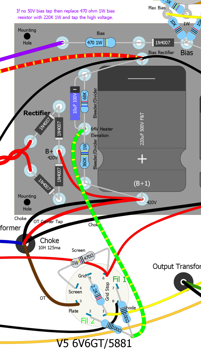
Source Bias Voltage From High Voltage
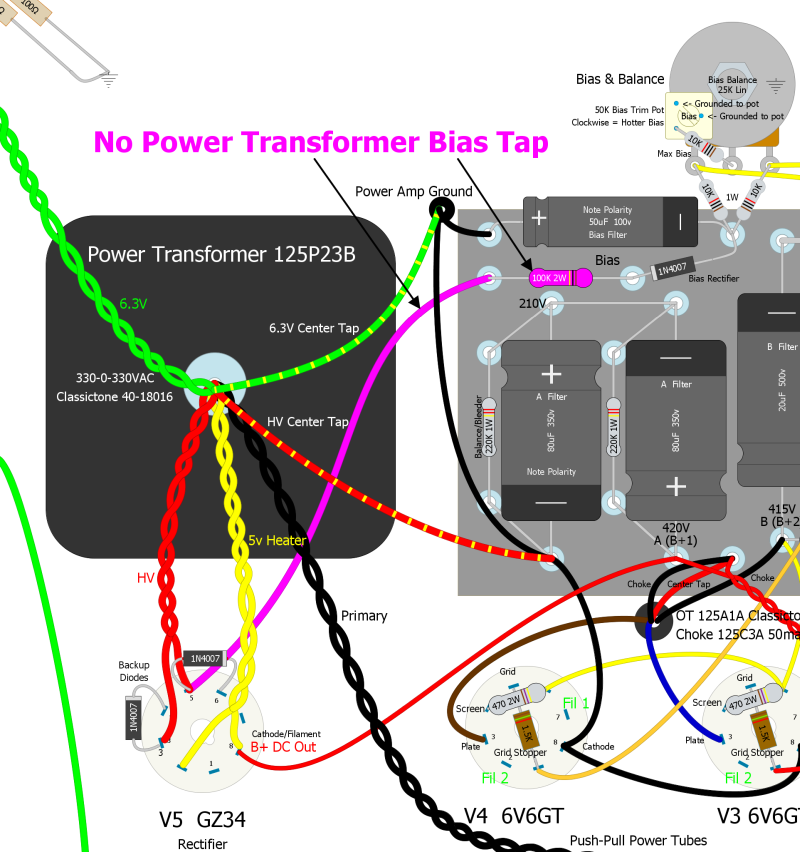
If your power transformer does not have a 50v bias tap you can use the above circuit to generate bias voltage from a power transformer high voltage lead. Tap into the power transformer high voltage at the rectifier. You must connect the bias tap wire to the same end of the diode as the transformer high voltage lead as shown above. The Bias resistor must be increased to 100k 2 watt. This bias circuit will only work with power transformers with a center tap.
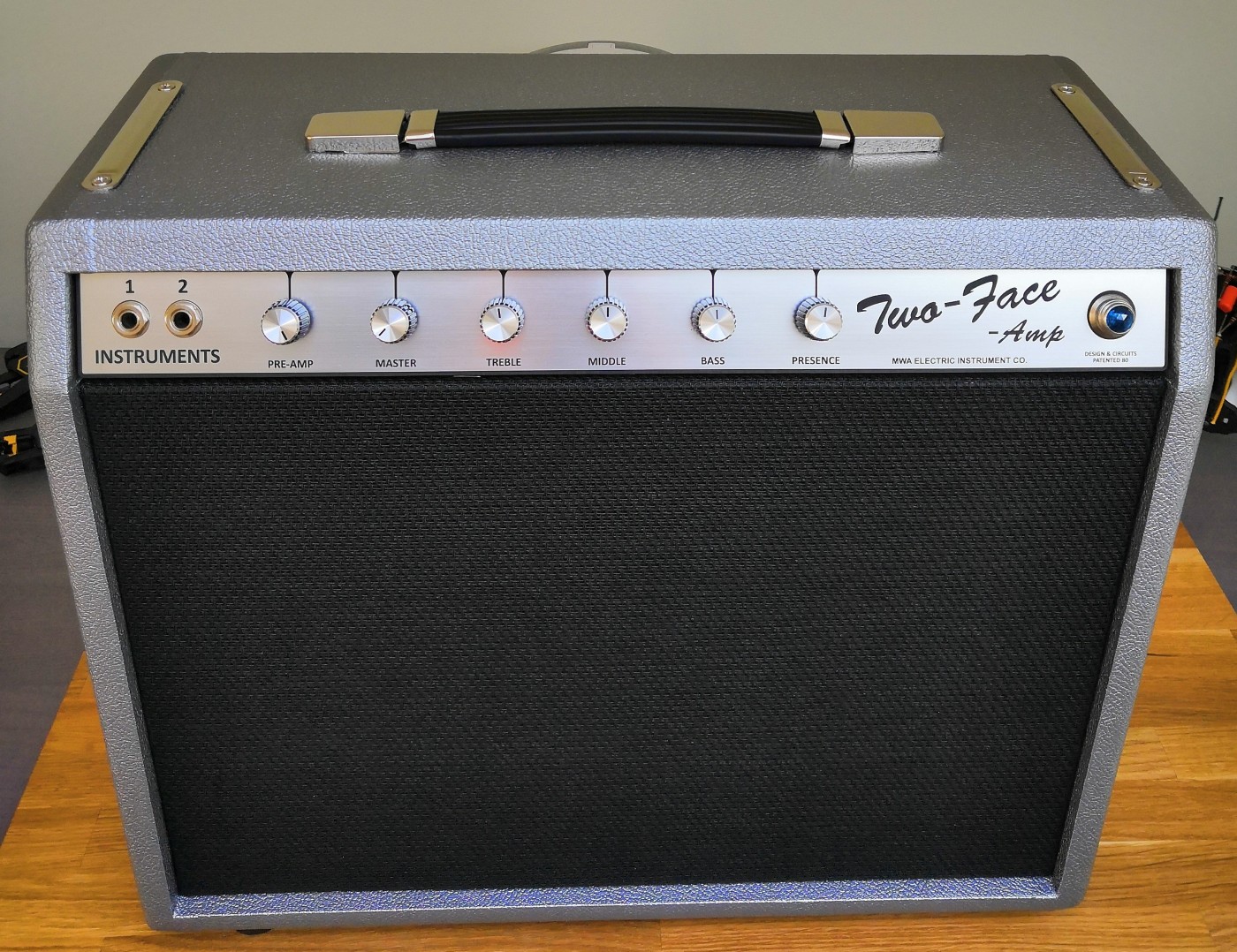
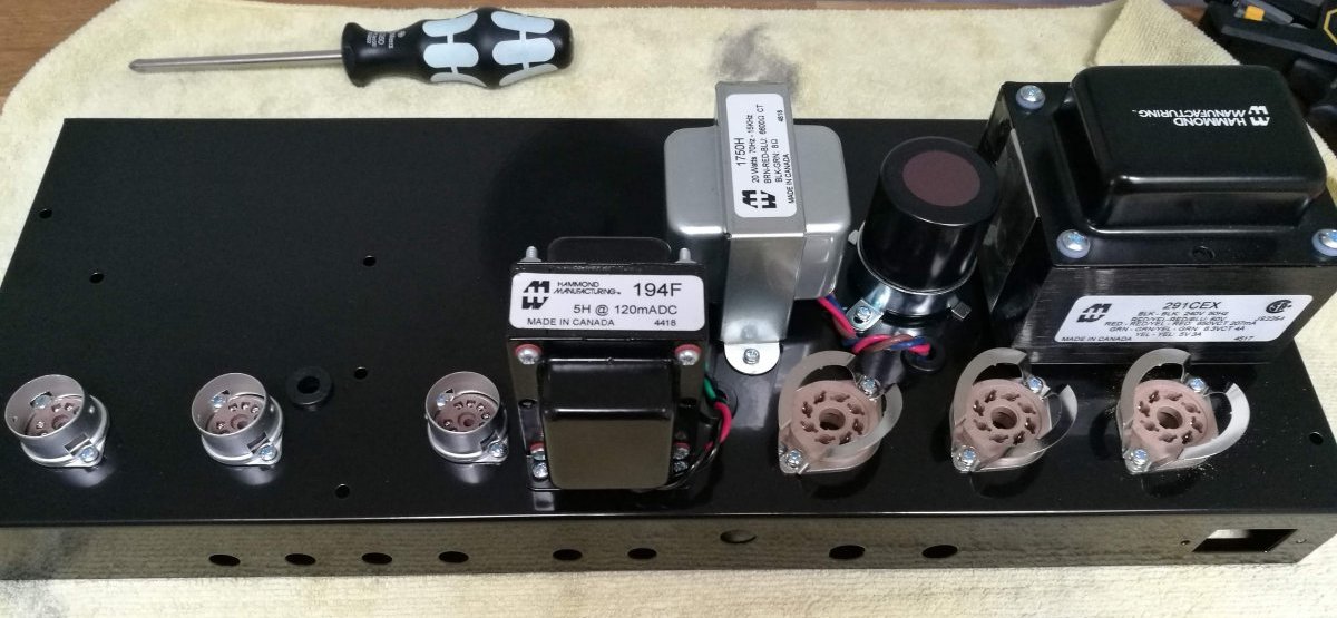
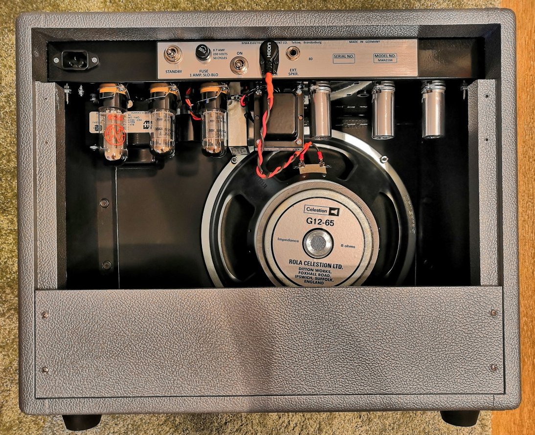
Another JCM800 6V6
Tweaking the JCM800 Overdrive Intensity and Tone
It's easy to adjust the JCM800 preamp overdrive and tone by changing the value of a few components. These tweaks apply to the factory Marshall Master Volume/2104, JCM800, my JCM800 6V6 and JCM800 Micro.
The two 470k Attenuator resistors highlighted in magenta below can be reduced to increase preamp gain and increased to reduce gain. The first Attenuator resistor and 1M volume pot form a voltage divider so increasing the Attenuator resistor will cut gain. Common values are 330k (for added gain), 470k (factory value) and 560k (for less gain). If 560k doesn't cut the gain enough then I recommend also adjusting the second Attenuator resistor located just before the 3rd preamp stage at the top of the circuit board (highlighted in magenta in the layout below). I left both Attenuator resistors at the factory value of 470k so try anything up to 1M to reduce preamp gain.
Increasing gain is more difficult in the JCM800 because the preamp is already pushed near the limit of stability. That's why many factory amps have a stability or "snubber" cap on the V1 tube socket. If you want to try for more gain you should start by adding that snubber cap, a 100pF to 270pF 600v+ ceramic disc cap across the first preamp stage pins 1 & 3 (plate & cathode) to add some stability. Trinity Amps Thör kit uses a 270pF snubber on V1A.
Reducing either Attenuator resistor from 470k to 330k will add gain. If you alligator clip a 1M resistor in parallel with the 470k you'll get 320k to see if you like the mod. 270k will probably be too much gain but you can give it a try by clipping in a 680k in parallel.
If you need to tame the JCM800 high end I recommend you start with reducing or removing the second 470pF Treble Peaker cap located on the upper right circuit board (highlighted in magenta in the layout below). Making the peaker cap smaller will raise the frequency cutoff of the high frequency bypass making the highs less prominent. Another option is to put a resistor in series with the peaker cap to lower the "volume" of the high frequency bypass. Try a 120k 1/2 watt and tune to taste from there. If you need even less highs you can remove or reduce the first Treble Peaker cap located between the Preamp Volume pot and Input jack from 470pF to 330pf or 270pF. The Bright cap on the Volume pot can also be reduced but keep in mind that cap only comes into play at lower volumes. It's there to keep the tone from getting too dark at lower preamp volume. Marshall used a .001uF Bright cap so common values used are 330pF and 270pF. You can also put a resistor in series with the Bright cap to lower the "volume" of the high frequency bypass.
If you just need to reduce a little ice pick then an Ice Pick cap around the NFB resistor can do that without too much side effect on the overdrive tone. Its value can range from 47pF to 470pF, a higher value will dip lower into the mid-highs for more high frequency reduction. You can alligator clip the cap in temporarily to find what you like.
If you are a very high gain player you can cut some low end by reducing the V1A bypass cap from .68uF to .47uF. This is actually a fairly common JCM800 mod. You can also decrease the value of the second Coupling cap (2nd coupling cap from the right on the circuit board) from .022uF to .0022uF. This lower value was used by Marshall in many factory Plexi, Master Volume and JCM800 preamps.
To simplify tuning preamp brightness consider building the amp without the Bright cap and Treble Peaker caps then add brightness in steps. Start by tuning the high gain tone by adding the second Treble Peaker cap, then if needed add the first Treble Peaker and find the right value for your taste. To trim ice pick add an Ice Pick cap around the NFB resistor. Then if the low volume tone is too dark add the Bright cap to the Volume pot and verify the high gain tone is still good.
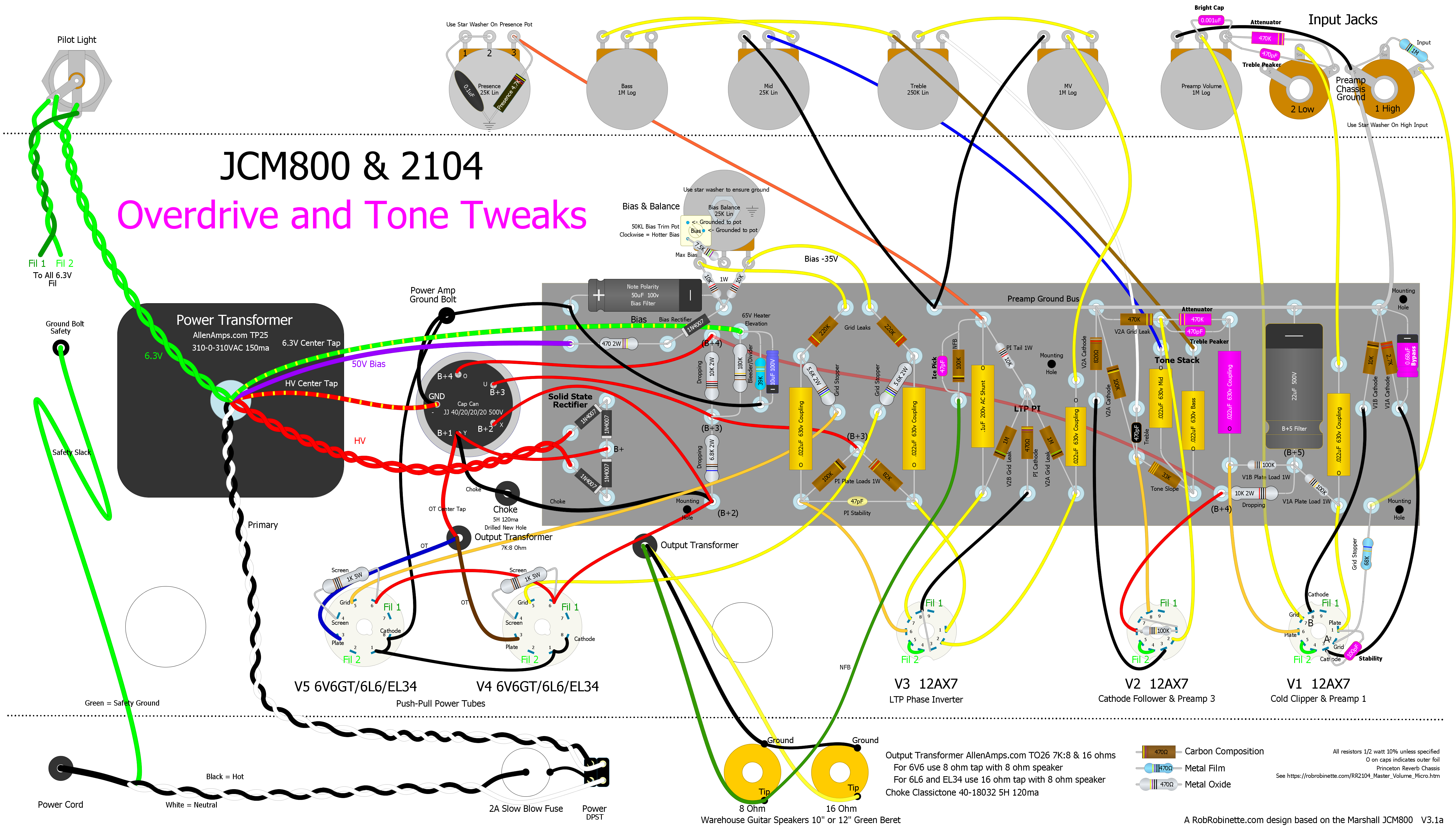
Tweaks in magenta.
Trinity Amps Thör Circuit Tweaks
Trinity amps sells a kit of my JCM800 6V6. It's a variant of their 18 Watt amp called the Thör. They made some minor circuit tweaks to tune the amp's tone and simplify the build. I have not evaluated these tweaks but wanted to let you know what they changed.
Thör Hi Channel Demo
Thör Lo Channel Demo
Thör Schematic
Thör Layout
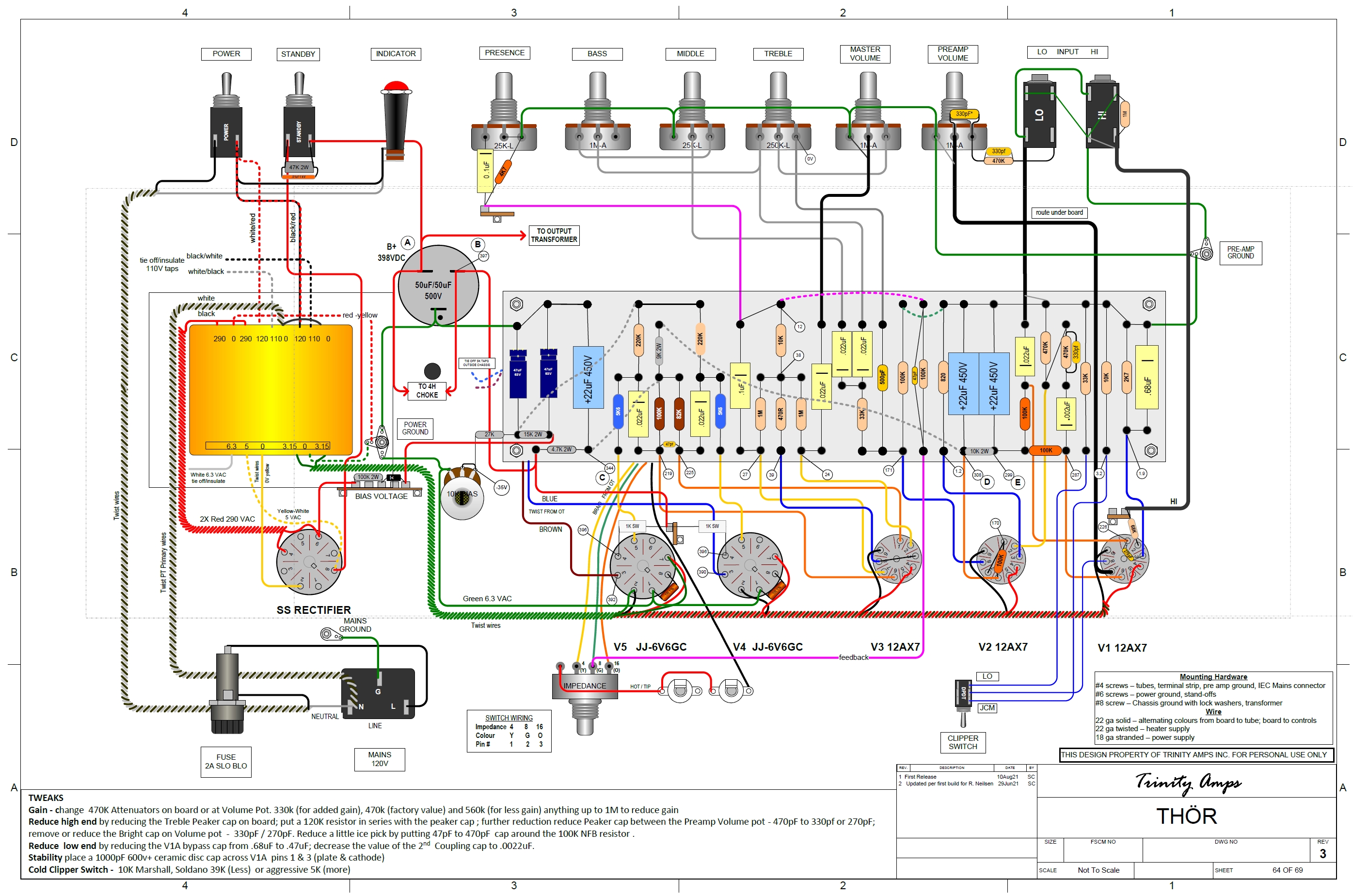
Thör Circuit Tweaks
Power transformer high voltage is reduced from 310-0-310v to 290-0-290v.
First power supply dropping resistor is reduced from 6.8k to 4.7k (needed since the power transformer voltages are lower). The second dropping resistor is reduced from 10k to 9k.
Both treble peaker caps reduced from 470pF to 330pF to tame the high end.
The bright cap across the volume pot is reduced from 1000pF (.001uF) to 330pF, again, to cut a little high end, especially at lower volume settings.
A 47pF ice pick cap is placed across the 100k negative feedback resistor to remove some ice pick highs.
Since the Trinity Amps power transformer does not have a dedicated bias voltage tap, they tapped bias voltage from one of the high voltage secondary wires so the first bias resistor is increased from 470 ohms to 100k 2 watt.
Deleted the bias balance circuit, added a second bias filter cap and used a 10KL bias pot.
Deleted the elevated heater center tap.
Installed a 270pF stability cap on V1A pins 1 and 3 to remove frequencies above human hearing to help prevent oscillation downstream.
JCM800 Micro 12AU7
Paul Rico's JCM800 Micro
Here's a sound clip from Paul's JCM800 Micro.
For this 1 watt Micro amp the following changes to the JCM800 circuit were made:
Large value power tube grid stop resistors are used and the grid leaks are reduced. The grid stopper and grid leak resistors have been rearranged to form a voltage divider to attenuate the phase inverter output to help the little 12AU7 triodes work as our power tubes without being overwhelmed.
The JCM800 power supply is modified to keep the little power tube happy. Since our triode power tube has no screens the screen power node is deleted. The choke is moved to smooth the entire amp's power supply.
The 6.3v heater center tap is elevated by connecting it to a Bleeder/Divider circuit at 65 volts. This heater elevation makes life much easier on the cathode follower and reduces heater hum (see layout below).
The NFB resistor has been reduced to 10k to compensate for the very low output voltage of the power amp.

All of the Micro changes are after the phase inverter. Click the schematic to see the high definition version. Download the schematic pdf here and the DIYLC file here.

Princeton Reverb chassis layout. The preamp ground bus is grounded at the High Input jack ground terminal. Power Transformer wires match the Classictone 40-18027 for 120v USA mains power. I used a few metal film resistors (light blue) for less hiss but left most carbon comp for mojo. The layout is an accurate depiction of a Princeton Reverb chassis. Click the layout to see the high resolution version. Download the layout pdf here, the DIYLC file here and the JCM800 Micro Hoffman circuit board DIYLC file here.
I recommend the use of a Princeton Reverb chassis and Classictone 40-18027 Princeton Reverb power transformer. The 40-18027 supports 120v and 240v mains and has two high voltage windings. We'll use the lower voltage 275-0-275v 100ma red-white high voltage leads which are perfect for the JCM800 Micro. The entire amp uses only about 30ma at idle. The power transformer has a 6.3v center tap so an artificial center tap is not needed. If you need a stand-up transformer to mount on top of a Hammond style chassis the Classictone 40-18085 is perfect.
You can also use a 250V (no center tap) 50ma+ power transformer with a bridge rectifier to power the JCM800 Micro (see below).
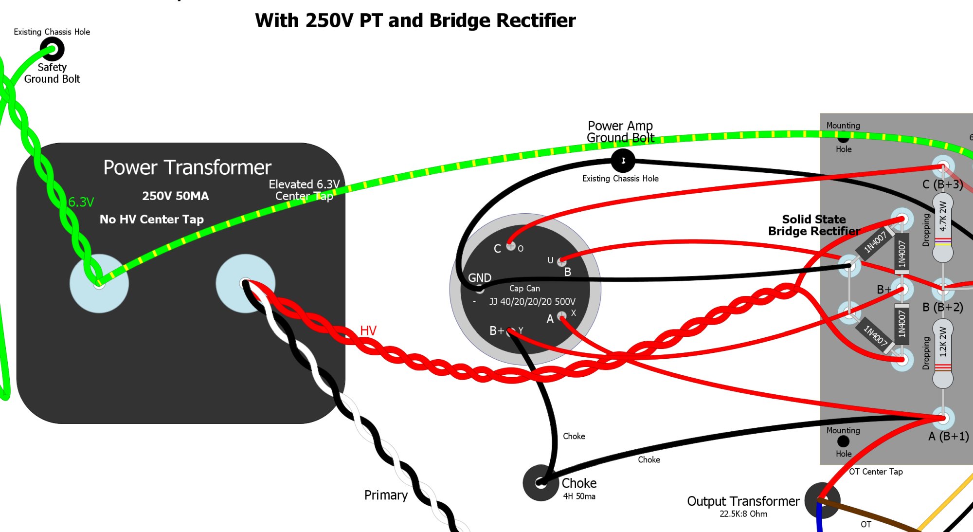
The 4 solid state 1N4007 diodes at the right are configured as a bridge rectifier and use a 250V 50ma+ power transformer with no high voltage center tap. Don't forget the jumper that ties the left side of the rectifier together for the ground.
6.3v Elevated Artificial Center Tap
If your power transformer does not have a 6.3v center tap then connect the 6.3v artificial center tap resistor junction to the 65v Heater Elevation eyelet (SLO-Nakid Micro shown).
The output transformer is a 5 watt rated Hammond 125B wired for 22.5K:8 ohms (use the orange and yellow secondary wires--do not connect the black wire). This little output transformer will give us some big amp transformer saturation for a little compression and sustain. I purchased mine from Mouser.com.
A Classictone 40-18040 4H 50ma choke easily supplies the entire amp with ripple-free power.
The cap can is a JJ 40/20/20/20uF 500v can. I sourced it and its clamp from Mojotone.com. The can's terminals are marked with Y, X, U, O and "-" stamped in the terminals. The Y terminal is 40uF and the X, U and O have 20uF. The "-" is the negative or ground terminal.
I've heard great things about the long plate JJECC802S 12AU7 as a power tube so give it some consideration.
You can upload the JCM800 Micro Hoffman circuit board DIYLC file to Hoffmanamps.com and Doug will make an eyelet or turret board for you. The empty board with eyelets or turrets installed is $18 + shipping. I used to make my own turret boards but with HoffmanAmps.com accepting DIYLC files to make custom boards it's just too easy and inexpensive to bother with making them myself.
You can use a standard Princeton Reverb size cab with either a 10" or 12" speaker. Mojotone sells a nice cab and a Princeton Reverb head cab too.
Circuit Tweaks
The choke is moved upstream to supply the entire amp with ripple free power. A 12AU7 based power amp is used for 1 watt of clean output power. Grid Leak and Grid Stopper resistors form a voltage divider to reduce the signal for our little power tube. Smaller value filter caps are used due to the very low power requirements of the amplifier.
A JJ Princeton Reverb 40/20/20/20uF 500v cap can is used for B+ through B+3 and a 20uF 500v cap is placed on the circuit board for B+4.
The 0.68uF V1A cathode bypass cap does not need to be an electrolytic. Any type of cap will work fine. I'm a fan of tantulum caps for .47 and .68uF bypass caps. The bypass cap should be rated at 10 volts or higher. A common mod is to reduce this bypass cap to .47uF to trim some lows from the high gain overdrive tone.
If your amp has stability and oscillation issues try chopsticking the amp leads around. Try to separate the preamp plate and grid wires as much as you can. If you still have stability and oscillation issues, placing a 1000pF (.001uF) 600v+ ceramic disc cap across V1A (first preamp stage) pins 1 & 3 (plate & cathode) will help. This stability disc cap is present in many factory Master Volume/JCM800 amps. The cap's purpose is to remove above-human-hearing high frequencies which reduces the probability of the amp going into oscillation.
If you are concerned about cathode follower grid-to-cathode arcing at startup you can connect this 120v neon bulb between V2B (cathode follower) pins 7 & 8 (grid and cathode). You can also use a 10k 1/2 watt resistor in series with a 1N4007 diode instead of the bulb. Connect the diode stripe (cathode) to pin 8 (cathode). If you start blowing V2 tubes then this is the fix you need.

JCM800 Micro signal flow begins at upper right at the High Input jack and ends at the speaker jacks and NFB circuit.
Speaker Suggestions
I'm not a fan of the Celestion G12T-75. I prefer the standard Celestion G12M Greenback for Marshall closed back cabs but for a JCM800 Micro combo cab my recommendation is the Warehouse Guitar Speakers Green Beret in 10 or 12 inch. I prefer the 10 inch speaker for Princeton Reverb cabs.
If you want a 12" speaker in a Princeton Reverb cab consider enlarging the cab. Adding two inches to the cab's width or height will allow a 12 inch speaker to breathe and not sound so boxy. Most cab makers will customize their cabs if you ask. The Green Beret is my top recommendation for a 12 inch speaker. The Celestion Classic Lead is also a good choice. I recommend the Celestion Vintage 30 if you like a slightly darker tone.
The overdrive intensity and tone tweaks in the JCM800 6V6 section apply to the JCM800 Micro too.
JCM800 Micro Bill of Materials
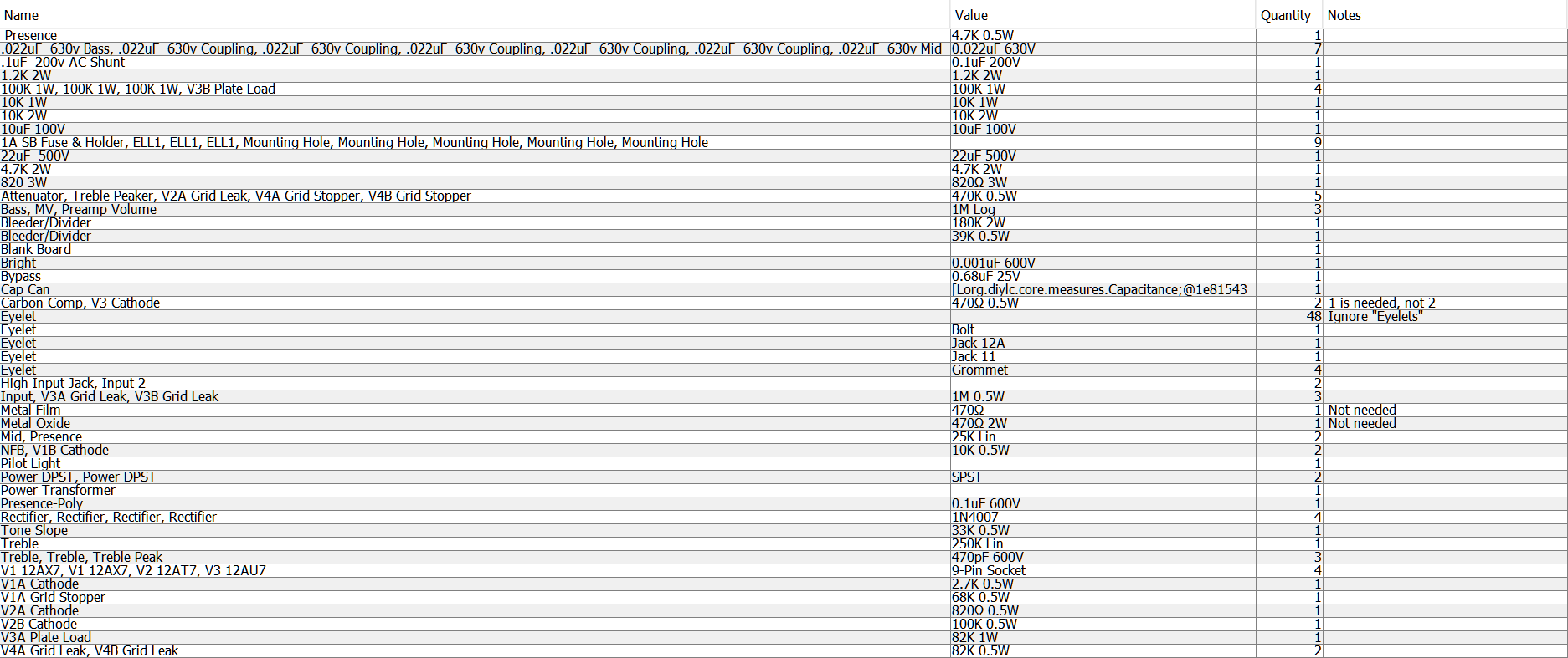
You'll also need a chassis, cab, speaker, power cord, wire, power and output transformers and choke. The 40/20/20/20uF 500v JJ cap can and mounting clamp came from Mojotone.com. For the hard-to-find 0.47uF cathode bypass cap I like this tantalum cap.
Classictone 40-18027 Power Transformer Wiring & Specs
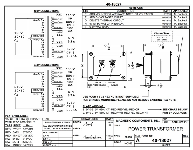
Note the 120v and 240v primary options. For 120v mains voltage we join the Black & Brown wires and we join the Black/White & Brown/White wires. For 240v mains we join just the Black/White and Brown wires. We'll connect the Red/White 550v high voltage wires to the rectifier tube. Shrink-tube the two unused red wires so they cannot touch each other or anything else.
Hammond 125B Output Transformer Wiring & Specs
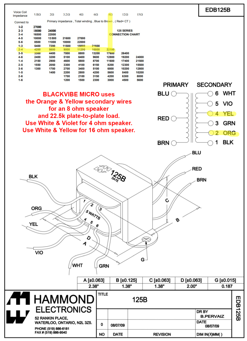
We do not use the Black secondary wire.
To summarize the parts sources I used: I purchased the Princeton Reverb chassis and most parts from Mojotone.com. I purchased the Classictone power transformer and choke from AmplifiedPartsDirect.com. I had to go to Mouser.com to get the Hammond 125B output transformer. Doug Hoffman at HoffmanAmps.com can supply the turret or eyelet board.
Rick Roy's JCM800 Micro
JCM800 Micro EF80 2 Watt
This is the 2 watt push-pull small pentode power tube version of the JCM800 Micro. It is designed to use a Princeton Reverb chassis. The preamp is still 100% JCM800 but the power amp was modified to run a pair of small 9-pin EF80 pentode power tubes in true push-pull. Builders have been asking for a micro power amp using a small pentode because pentode overdrive tone is different than triode overdrive tone. A pentode's screen grid generates a distinct power tube distortion so this power amp should sound more like a full size amp than one using triode power tubes such as the 12AU7.
The power transformer, power supply and output transformer were changed to suit the EF80 power tubes. The power tube grid stop and grid leak resistors were rearranged to form an attenuating voltage divider that dumps 90% of the signal to keep from overwhelming the little power tubes. The NFB resistor value was decreased to compensate for the lower output transformer secondary voltage.
My recommended power transformer is the $28 AnTek AS-05T200 toroidal power transformer 200v @ 130ma (50VA), 6.3v @ 4 amps. It must be used with a bridge rectifier. You can build the bridge rectifier with two tag strips and four 1N4007 diodes or get an inexpensive bridge rectifier like this $1 three amp 1000v bridge rectifier from Mouser. The AS-05T200 has both 120v and 240v primaries. It also has a 180v tap in case you want to lower the amp voltages (use gray and yellow wires for 180v of HT). Another bonus is it only weighs 2 lbs. Size is 3.75" in diameter and 1.6" tall. You can mount the transformer on the top of the chassis and purchase a 105x45mm round transformer cover, leave it exposed or mount it inside. Mounting consists of drilling a single hole for the transformer central bolt.
![]()
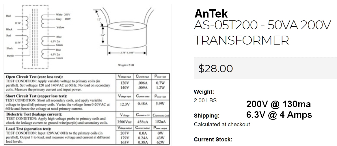
Detailed AnTek Wiring
![]()
If you would prefer to use a "normal" (non-toroid) power transformer then I suggest the $89 Hammond 269EX 190-0-190V power transformer with 190-0-190 high voltage at 75ma, 2.5 amps of 6.3v heater current. For international builders I recommend the Hammond 369EX which has 100, 110, 120, 200, 220,230, 240 VAC 50/60 Hz primaries. The 269EX/369EX is a good choice for any amp using an EF80 power amp but it does not include a 5v secondary so if you want to use a tube rectifier use an EZ81 (6.3v).
Hammond 269EX/369EX Power Transformer
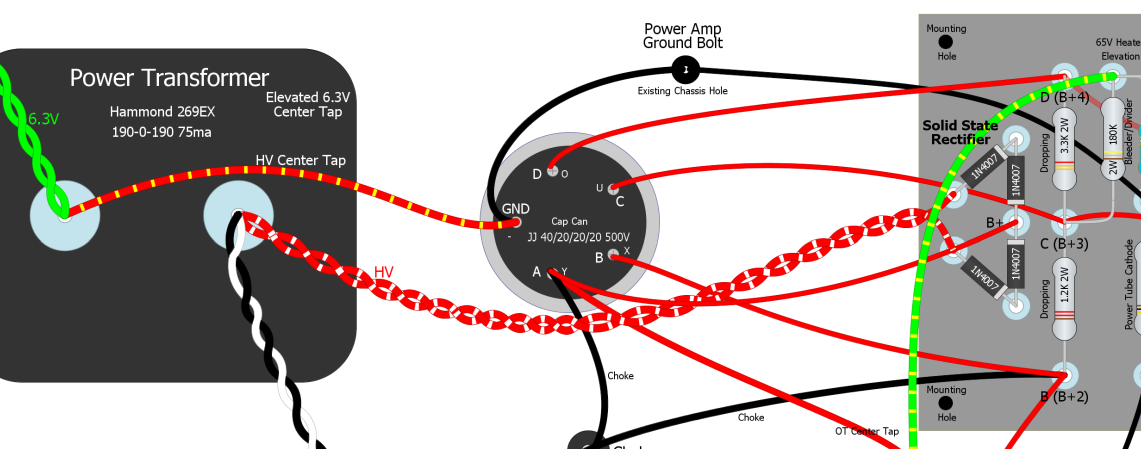
Note the position of the HV center tap and the full wave conventional rectifier wiring.
New Old Stock EF80s (also called 6BX6) are inexpensive ($6) and plentiful but tend to be microphonic so they are best used in head amps and not combo cabs. If you do use them in a combo cab expect to have to try several tubes to find a pair that are not microphonic. Using rubber insulated sockets and silicone damping rings on the tubes may help with microphonics. The EF80 uses standard 9-pin sockets and 6.3v heaters so they are easy to implement into a modern amp build.
At 270 to 300v on the plates and a 300 ohm cathode resistor (as in the layout below) you can expect about 5.2v across the cathode resistor with the EF80s running at 2.45 watts, 95% plate dissipation with 8.4 milliamps of plate current per tube. Adding a 1k 1/2 watt screen resistor will add some screen sag distortion and emphasize the difference between triode and pentode overdrive.

Princeton Reverb chassis layout. V4 & V5 are EF80 nine-pin pentodes in true push-pull fed by an LTP phase inverter for 1 watt of output power. EF80 socket pins 1 (cathode), 9 (suppressor grid) and 6 (internal shield) are tied together. B+2 is connected to pins 8 (screen). A 300 ohm 3 watt cathode resistor is used. Output transformer is the same Hammond 125B 22.5K:8 ohm and 5 watts as used in the 12AU7 version. The preamp ground bus is grounded at the High Input jack ground terminal. I used a few metal film resistors (light blue) for less hiss but left most carbon comp for mojo. The layout is an accurate depiction of a Princeton Reverb chassis. Click the layout to see the high resolution version. Download the layout pdf here, the DIYLC file here and the JCM800 Micro Hoffman circuit board DIYLC file here.
The output transformer is a 5 watt rated Hammond 125B wired for 22.5K:8 ohms (use the orange and yellow secondary wires--do not connect the black wire). This little output transformer will give us some big amp transformer saturation for a little compression and sustain. I purchased mine from Mouser.com.
The choke is a Hammond 155H 5H 50ma.
The cap can is a JJ 40/20/20/20uF 500v can. I sourced it and its clamp from Mojotone.com. The can's terminals are marked with Y, X, U, O and "-" stamped in the terminals. The Y terminal is 40uF and the X, U and O have 20uF. The "-" is the negative or ground terminal.
You can upload the JCM800 EF 80 Micro Hoffman circuit board DIYLC file to Hoffmanamps.com and Doug will make an eyelet or turret board for you. The empty board with eyelets or turrets installed is $18 + shipping. I used to make my own turret boards but with HoffmanAmps.com accepting DIYLC files to make custom boards it's just too easy and inexpensive to bother with making them myself.
You can use a standard Princeton Reverb size cab with either a 10" or 12" speaker. Mojotone sells a nice cab and a Princeton Reverb head cab too.
If you like this amp but want even more cowbell see the SLO-Nakid Micro EF80 (Soldano SLO-100 Micro).
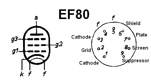
Pins 1 & 3 connect to a single cathode, pins 4 & 5 (f) are 6.3v heater filaments, pin 6 is an internal shield which is normally connected to the cathode or ground, pins 1 & 9 (cathode and suppressor grid) are normally tied together.
Hammond 125B Output Transformer Wiring & Specs
For the EF80 we want 22,500:8 ohms so we use the Yellow (4) & Orange (2) wires. We do not use the Black secondary wire.
![]()
Another (better looking) option for the output transformer is the $29 MusicalPowerSupplies.com OT5PP 22.5K:4-8-16 ohms.
Bill of Materials
You will also need a Hammond 125B output transformer, Hammond 155H choke, chassis, cab, speaker and power cord.
To summarize the parts sources I used: I purchased the Princeton Reverb chassis and most parts from Mojotone.com. I purchased the choke from AmplifiedPartsDirect.com. I had to go to Mouser.com to get the Hammond 125B output transformer and Hammond 269EX 190-0-190V power transformer. Doug Hoffman at HoffmanAmps.com can supply the turret or eyelet board.
EF80 Power Amp

This is the Blackvibe Micro EF80 but the power amp is identical to the JCM800 Micro EF80.
JCM800 Micro EF80 Quad
This is the four EF80 parallel/push-pull version of the JCM800. We add two power tube sockets, parallel them, and reduce the output transformer impedance by half to 11.6k:8 ohms using the Hammond 125B output transformer yellow and black wires (see Hammond impedance chart). That's all that's required to run four power tubes. The PT and OT can handle the two extra tubes, no problem.

Quad EF80 power amp using 11.6k output impedance will output around 4 watts. Cut or punch two 9-pin socket holes, or cut one and use one of the 8-pin socket holes with a novel adapter (8 to 9-pin hole adapter). Click the layout for the high resolution version. The PDF is here. Download the .diy layout file here.
The Full Size Marshall 2204/JCM800
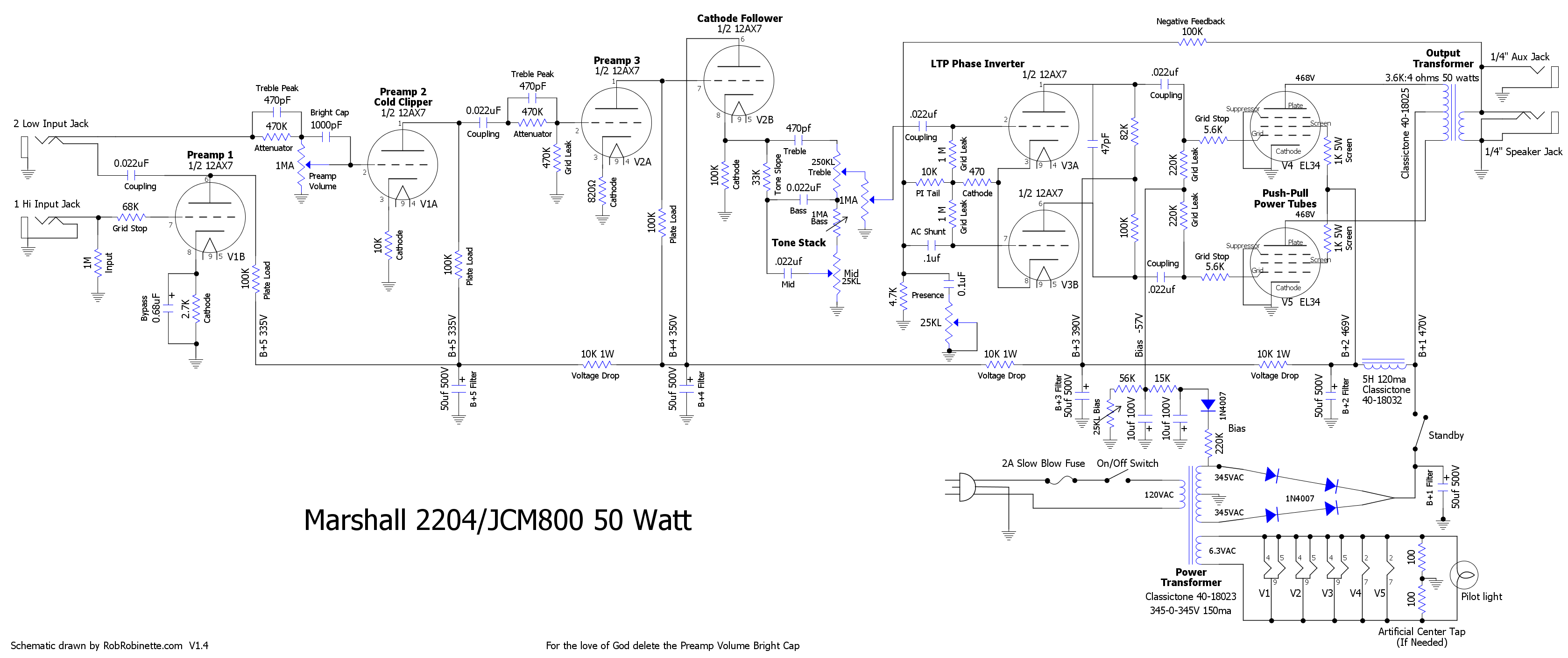
Click the schematic to see the high resolution version. Download the schematic pdf and DIYLC file.