[ Robinette Box ] [ Resistor Network Calculator ] [ Balanced Cables ] [ Balanced vs Unbalanced ] [ Headphone Amp ]
Fostex T50RP, AKG K240, K701, K702, Q701, K712
Sennheiser HD 580, 600, 650, 6XX
HiFiMan HE-400, HE-500
Headphone Balanced Wire Mod
By Rob Robinette
The AKG Headphone Balanced Mod is here.
The Sennheiser HD HD580, 600, 650 & 6XX Balanced Cable mod is here.
The HiFiMan HE-400 and HE-500 Balanced Cable mod is here.
The Balanced Wire Headphone Cable DIY is here.
The Robinette Box Headphone-to-Speaker Amp Resistor Network Interface is here.
After doing some of the standard mods to my Fostex T50RP I decided I wanted to add the capability to use a balanced line headphone cable to connect to amplifiers that offer balanced output. Most headphone amplifiers offer only a stereo TRS plug connection because they have common ground output. Common ground output means the right and left channels' negative outputs are simply connections to ground. The left and right negative signals are combined in the headphone and travel down the headphone cable's metal shield to the amplifier's ground. The left and right stereo signal's positive connections are carried by two separate wires that are wrapped by the headphone cable shield. The headphone cable's grounded shield not only acts as the stereo signal return path but also protects the stereo signal from radio frequency interference (RFI) noise. This type of headphone cable is called unbalanced or single-ended.
A balanced stereo line uses a headphone jack with 4 connections and the headphone cable has 4 wires of equal size to carry the stereo signal. The 4 wires are for: Left +, Left -, Right + and Right -. A 4 wire balanced line rejects RFI naturally due to each stereo channel's two equal length and gauge wires both picking up the same electrical noise--one wire is positive and the other is negative so when the signal from the two wires is combined at the speaker the added noise cancels itself out. Adding a grounded shield to a balanced line will offer even more noise rejection and radio magnetic interference (RMI). For more information on balanced line theory and benefits see this wikipedia article.
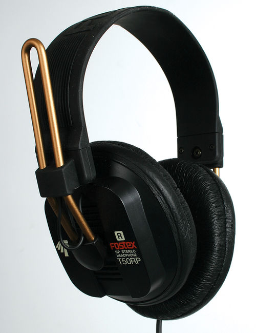
Unmodified T50RP
The Mad Dog Balanced version of the T50RP uses a Sam Woo Electronics SN-8-4(R) receptacle jack and SN-8-4(P) cable plug from Evalucon. I could find no other source for the SN-8-4 connector.
Mad Dog Balanced Line Modified T50RP
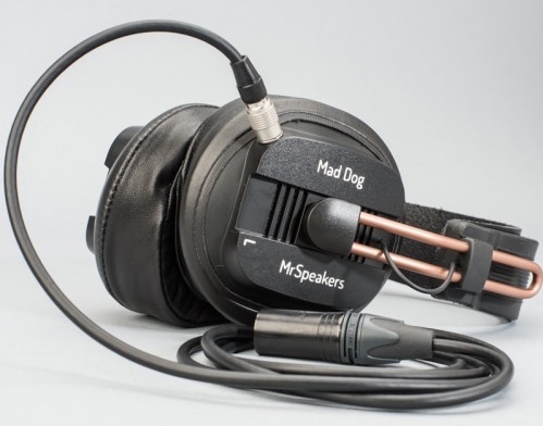
Note theSN-8-4(P) connector on the headphone and the full size Male 4-Pin XLR connector. Mad Dog headphones are available from MrSpeakers
My Balanced Cable Setup With 4-Pin Mini XLR
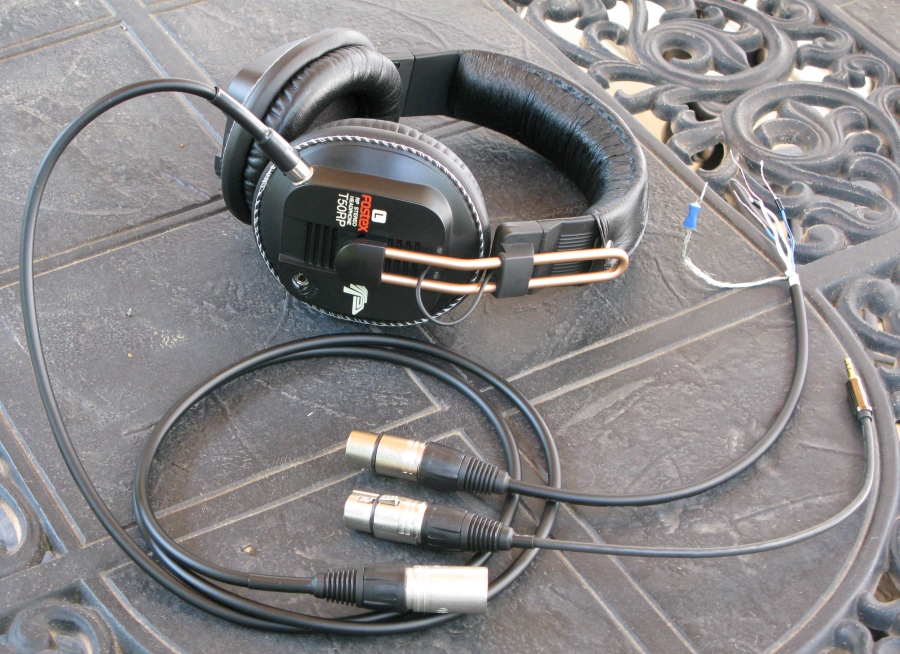
Headphone cable has a 4-Pin Female Mini XLR at the headphone and 4-Pin Male XLR at the amp end. Adapters are for speaker out (upper) and unbalanced 3.5mm stereo plug.
Sam Woo SN-8-4(P) Plug
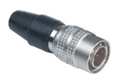
Mr Speakers uses this connector on his Mad Dog Balanced headphones.
Instead of using the SN-8-4 connector used on the Mad Dog Balanced headphone I chose to use a Male 4-Pin Mini XLR chassis connector because it's an easily sourced standard audio connector and it's small enough to fit on the headphone. It is mounted in the same place as the Mad Dog's shown above on the forward lower corner of the left ear cup.
I drilled a 1/8" hole as a pilot hole to verify the hole's position inside the cup. I then chose a drill bit slightly smaller than the Mini XLR jack and then slowly enlarged the hole until I got a nice tight fit with the jack. I oriented the jack so the cable's release button would be facing the rear the same way AKG does it. This way when you're wearing the headphones your thumb can easily find the button to release the cable.
Originally I was planning to leave the headphone's standard 1/8 inch (3.5mm) connector in place for flexibility and solder the 4 new balanced wires to the 3.5mm jack inside the ear cup but when I opened the headphones I realized the 3.5mm jack combines the two negative signal lines (both headphone white wires are connected together at the jack) which would cause a problem for the balanced line. You could install a micro-switch in the top rear corner of the ear cup to disconnect one white wire from the 3.5mm jack for balanced cable operation. The switch would allow you to switch between the headphone's single-ended and balanced jacks but for simplicity's sake I decided to discontinue use of the 3.5mm jack and just solder the original driver wires to the new 4-Pin Mini XLR jack.
Headphone Driver Wires
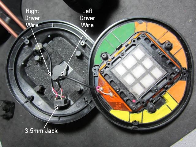
Each driver (speaker) has a Red + and White - wire.
Connecting the headphone driver's 4 wires to a 4-pin jack is all that's required to make the balanced line work and it's an easily reversible mod if you decide to go back and use the original 3.5mm jack. Each driver (speaker) in the headphone has a red and white wire. I wired the red wires as the + wires and the white wires as the - wires. I used industry standard stereo audio 4-pin XLR pinout for the headphone jack and both ends of the headphone cable. Most XLR connectors have the pin numbers molded into the plastic connector--they're small but they're usually there.
Wire the Headphone Male 4-Pin Mini XLR Jack
Standard Stereo Audio 4-Pin XLR Wiring
Pin Signal Wire Color
1 Left + Left ear cup red wire
2 Left - Left ear cup white wire
3 Right + Right ear cup red wire
4 Right - Right ear cup white wire
Note: All 4-Pin XLR connections (mini, full size, male and female) follow the above pin mapping. The Mad Dog Balanced headphone also follows this standard.
Male 4-Pin Mini XLR Chassis Mount
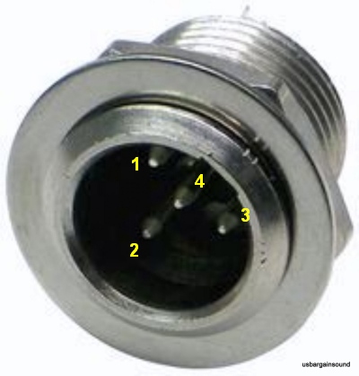
This chassis mount connector is installed on the headphone's left ear cup. Remember pins 1 & 3 will be on the opposite side when you view the connector from the rear to solder the wires.
Important: Tin the wires and XLR pins (put a little solder on them) before you join the wires to the pins. This will make it much easier to get a good solder joint between the wire and pin. Using a pointed solder tip will make soldering the small Mini XLR pins easier.
Details on building or buying a balanced cable are here.
AKG K240, K701, K702, Q701 and K712 Studio Balanced Wire Mod
If you have AKG K701 headphones your stock cable is a 4-wire so all you have to do to convert it to balanced mode is cut off the stereo TRS plug and solder on a Male 4-Pin XLR connector. Follow the directions here.
Changing the AKG K240, K702, Q701 and K712 headphones to balanced operation is pretty easy because all you have to do is replace their 3-Pin Mini XLR Male plug with a 4-Pin version and then make or buy a 4 conductor headphone cable. You'll need to purchase a Male 4-Pin Mini XLR connector but the only part you really need is its 4-pin plug (the part that gets soldered).
To open the headphones you have to remove the gold, "Made in Austria" medallion on the left ear cup. It is much easier to get off if you apply some heat with a blow dryer or a heat gun on low (be careful, the plastic parts of the headphone can bubble or melt if you get them too hot). Use a knife blade to carefully pry up one end of the U shaped emblem and then gently pull it entirely off. The warm glue will still be sticky so you can put it back on later very easily.
With the emblem off you'll see the two small screws that hold the ear cup cap on. Remove the screws and put them somewhere so you won't lose them. It's easy to get the Mini XLR 3-pin plug out of the ear cup cap. Just stand the cap up with the 3-pin jack facing up and use a small punch or thin screwdriver to tap it down and out. The pic below shows the 3-pin plug after it was tapped out of the ear cup cap.
Ear Cup Cap Removed
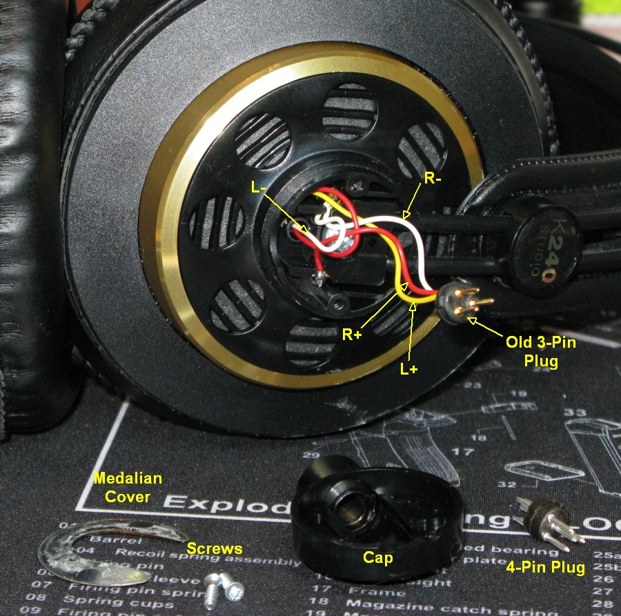
Note the emblem at the bottom left, screws, ear cup cap and new 4-pin plug on right. Also note the L- wire must be disconnected from the R- wire at their common solder joint.
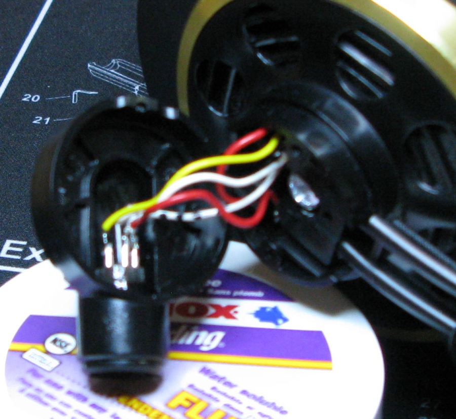
Notice how there are 3 wires attached to the 3-pin plug, a red, yellow and white wire. The red wire is R+ (right +), the yellow is L+ and the white is a combined ground (R & L -). If you trace the white wire back to it's solder joint you'll see there's a second white wire attached at that point--that's the L- wire. The white wire that goes all the way to the plug is the R- wire. You need to de-solder the L- wire so you can attach it to the new 4-pin plug. Pull on the L- wire with tweezers while you touch the solder gun tip to the solder joint. The solder will melt and the wire will pull free. Mark this wire with a marker so you can tell it from the R- white wire. To help identify left from right note that both right driver wires are connected to the headphone headband support wires. The signal is sent to the right ear cup through the headband support wires.
De-solder the three wires from the old 3-pin plug. Again, just pull on a wire and melt its solder to get it off the plug pins.
4 Wires Ready for the 4-Pin Plug
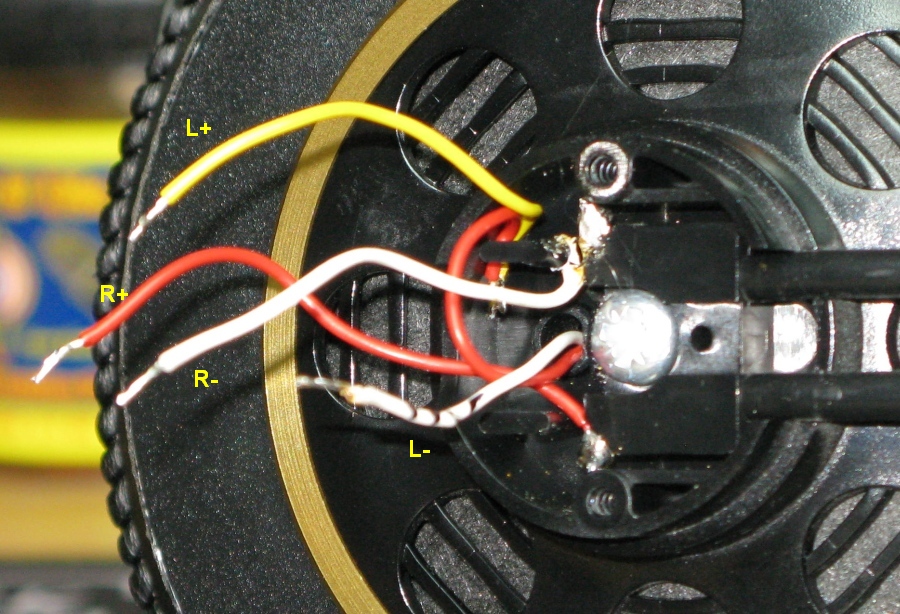
The L- white wire has been de-soldered and marked to distinguish it from the R+ white wire.
The new 4-pin plug should have the pin numbers on the plastic plug. I used standard stereo audio 4-pin wiring.
Pin Signal Wire Color
1 L+ Yellow
2 L- White (with mark)
3 R+ Red
4 R- White
Important: Tin the wires and XLR pins (put a little solder on them) before you join the wires to the pins. This will make it much easier to get a good solder joint between the wire and pin. Using a pointed solder tip will make soldering the small Mini XLR pins easier.
4 Wires Soldered to the 4-Pin Mini XLR Male Plug
Sorry about the blurry pic.
With all 4 wires connected to the new 4-pin plug test the connection by connecting a Female 4-pin Mini XLR cable. Be very careful not to pull on the wires during the test. After a successful test slide the plug into the ear cup cap. The plug has an alignment tab that must fit into a groove to allow the plug to slide down into it's jack hole (yea, I said "jack hole" ;) ). While holding the plug in the fully seated position apply one drop of super glue to secure the plug into its hole. Give it some time to dry before reassembling.
Reinstall the ear cup cap on the headphones making sure no wires are pinched. Install the two screws and press the medallion back into place. You may need a little glue to secure it but don't over do it in case you need to remove it again in the future.
Details on building or buying a balanced cable are here.
Rob Robinette