S2000 Valve Adjustment
By Rob Robinette
Valves clearances usually "tighten up" (smaller clearance) with wear. As the valves bang up and down the valve face smacks into the valve seat and eventually wear each other down. When this happens the valve sits deeper into the seat which raises its stem toward the rocker--so tighter clearance. If your valves are tight then opening up the gap to specs could actually cause a little more noise as the rocker "strikes" the valve stem harder with the wider gap. But it's not uncommon to find valve clearances both tighter and looser than spec and the engine will usually run quieter after an adjustment.
Replacement Parts Needed
If your engine is older than about 5 years it would be a good idea to replace the:
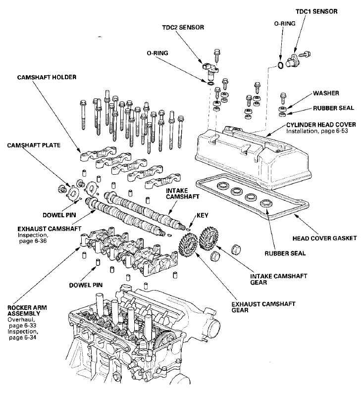
Cylinder Head Cover Gasket
Cylinder Head Cover Bolt Rubber Seals (5)
Spark Plug Hole Rubber Seals (4)
Special Tools Needed
5/8" (16mm) Spark Plug Socket
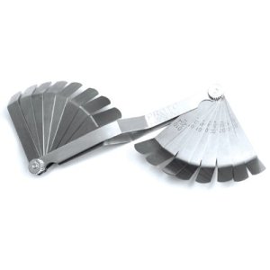
Set of bent feeler gauges (you will not be able to feel the gap drag with straight feelers)
Craftsman Feeler Gauge Set $15
10mm Valve Adjustment Tool From Amazon For $11
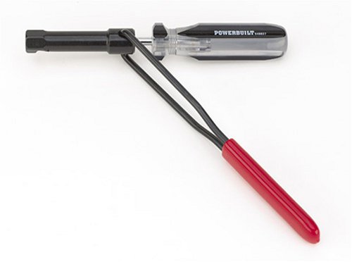
It's a combination screwdriver & 10mm socket, not completely necessary but highly recommended.
Remove the Ignition Coil Cover
The engine must be cool (below 100 degrees F) to accurately adjust the valve clearances. It's best to let the car sit overnight.
Use a 10mm socket for the front ignition coil cover bolt and to loosen the passenger side TDC2 sensor bolt located near the firewall. Use a hex wrench to remove the 4 hex head bolts and remove the cover.
Remove the Cylinder Head Cover
Note: Only TDC1 Sensor Must Be Removed From Cylinder Head Cover
Recommended Reading
Remove the Cylinder Head Cover
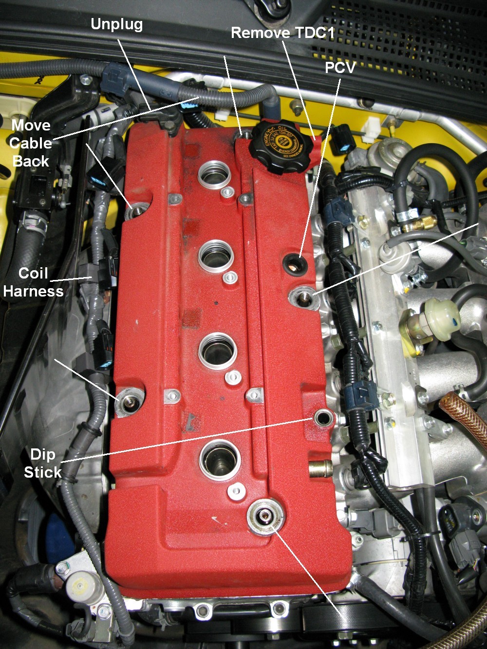
Unclip the thick electrical cable that runs above TDC2 from its firewall bracket (shown below as "Move Cable Back").
Unplug the electrical connector from the passenger side TDC2 sensor (upper left below). The sensor can stay bolted into the head cover.
Unplug and remove the driver side TDC1 sensor. It is held in by 1 10mm bolt. Gently rock the sensor back-and-forth and it will pull free. Inspect its rubber o-ring.
Remove the 4 10mm coil pack bolts.
Disconnect the 4 coil pack connectors and remove the coil packs.
Gently move the coil harness off to the passenger side of the cover (see below).
Remove the 5 10mm head cover bolts and pry up the washers and rubber seals beneath each of them. Watch the washers, they will fall off the rubber seals.
AP1: Pop the PCV valve out of its hole. AP2: Remove the hose from the PCV valve.
Remove the dip stick.
Remove the fuel rail cover. It has two 10mm black acorn nuts securing it.
Remove the spark plugs. Do this last to keep from dropping something down the spark plug hole.
The Cylinder Head Cover is now ready for removal. I gently hit my cover with a rubber mallet to get it loose. Once loose you can rock it back-and-forth to get free of the spark plug hole seals. You must push the thick electrical cable on the firewall back and down out of the way so you can lift the cover off.
Once off inspect the spark plug rubber seals and the cylinder head cover gasket.
Cylinder Head Cover Ready to Lift Off
Cylinder Head Cover Off
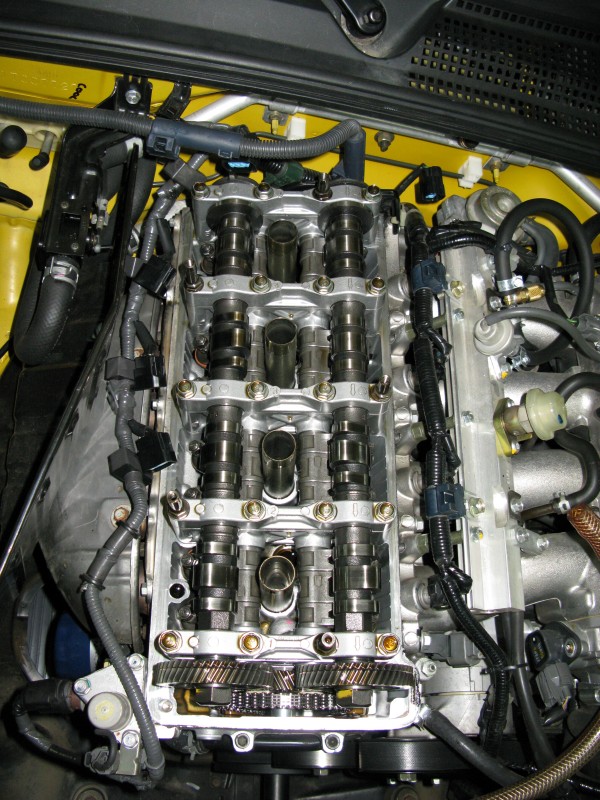
Consider Removing Heat Shield
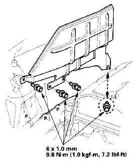
Note: Rearmost Bolt Only Needs To Be Loosened
Valve Adjustment Specs
![]()
Set Top Dead Center (TDC) for Cylinder # 1
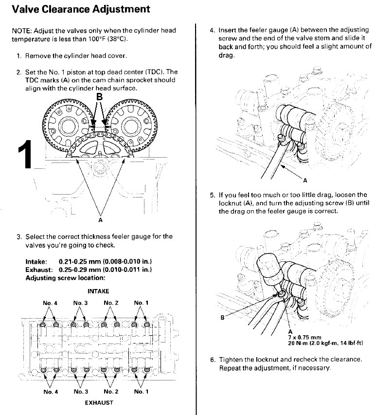
Note the position of the cam gear timing marks highlighted as "B" above. They are more accurate than the marks on the cam chain sprocket.
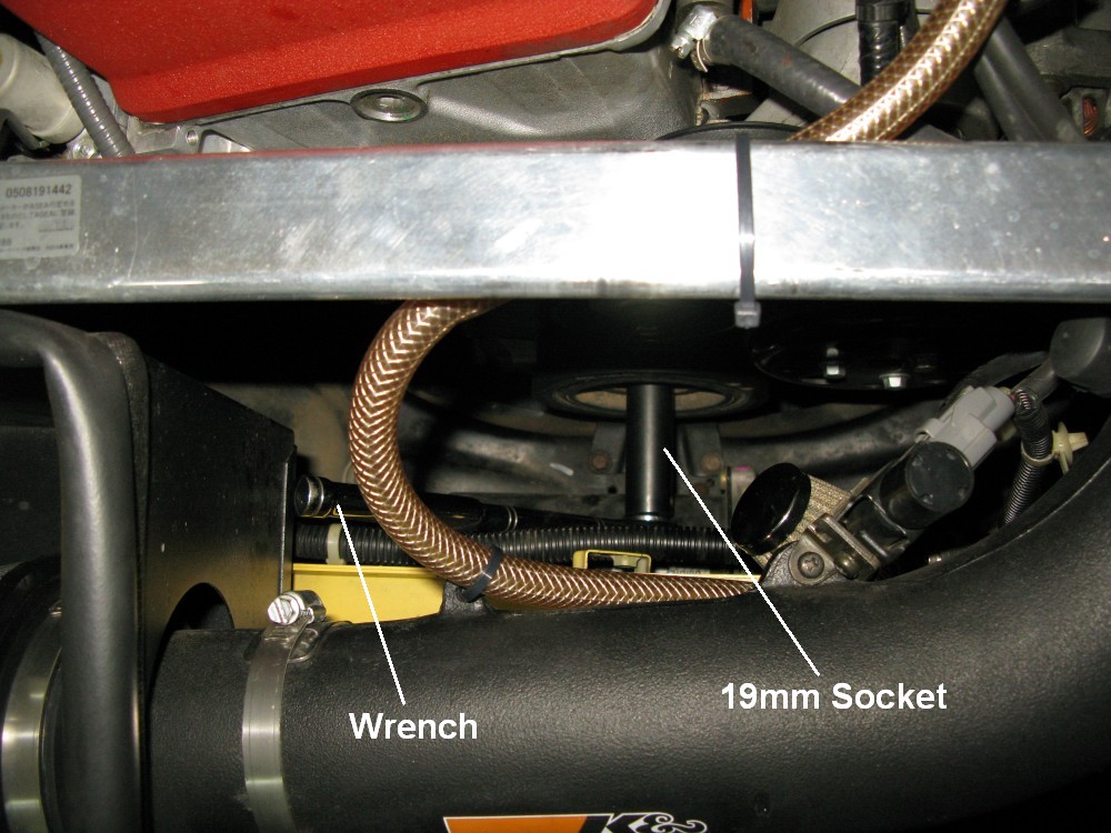
Using 19mm Socket & Wrench to Turn Crank to Set TDC
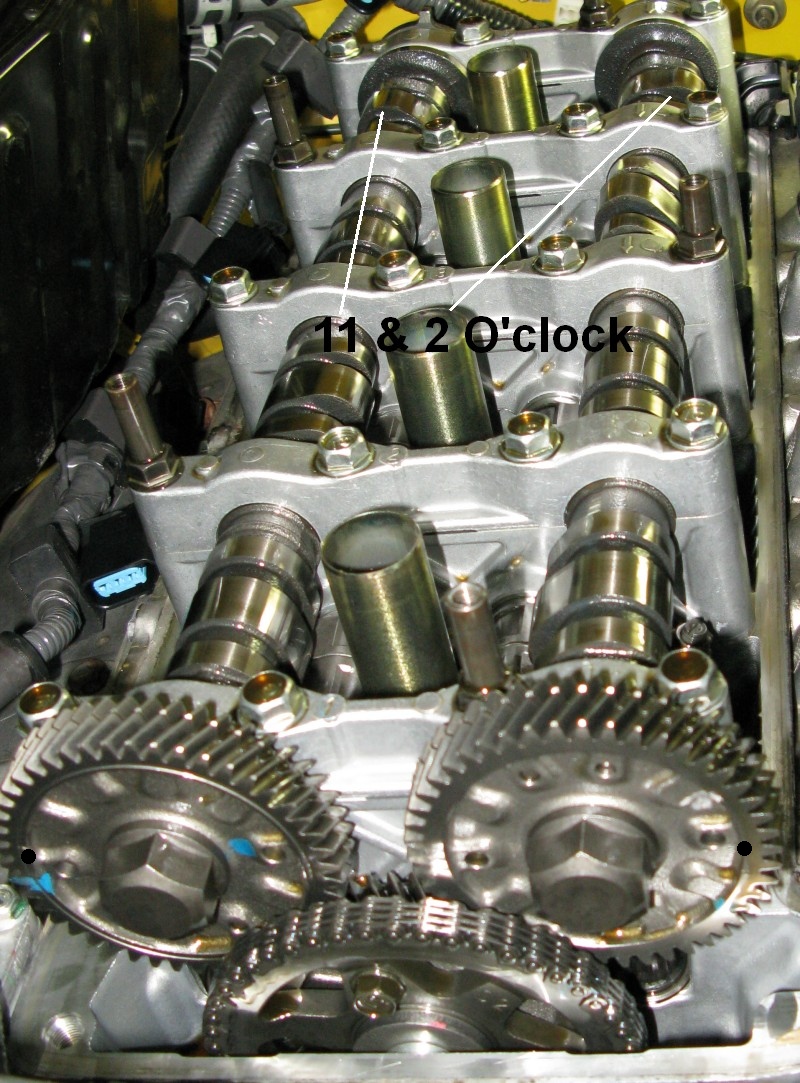
TDC Set for Cylinder #1
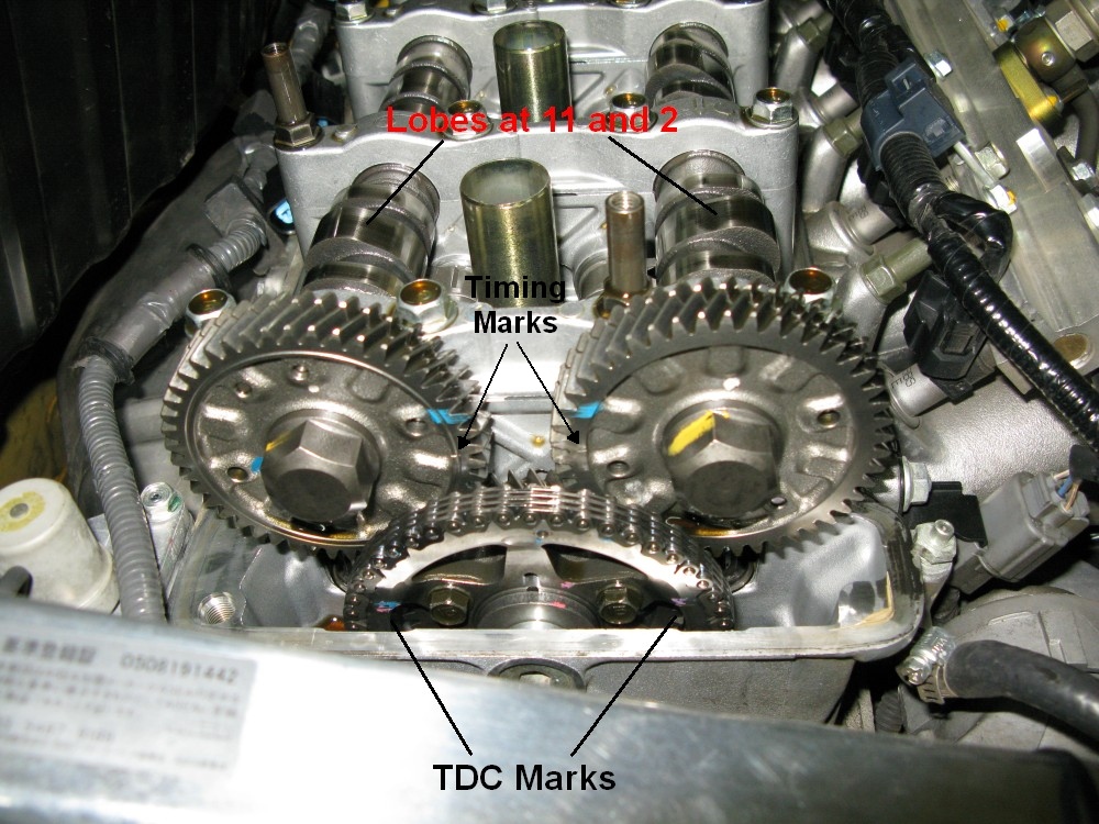
Note the timing marks on the cam chain sprocket and cam gears. #1 Cam Lobes are at 11 and 2 O'clock
Make sure the car is in neutral and use a 19mm socket and wrench to turn the crankshaft to line up the TDC marks and #1 cylinder cam lobes as shown in the above picture. Once TDC is found for cylinder #1, moving to TDC for the other cylinders is as follows: 180º degrees more clockwise turn of crankshaft gives TDC for #3, 180º more gives TDC for #4, 180 more gives TDC for #2 (so do the cylinders in that order). When the crankshaft is turned 180º the cam gears will turn 90º so watch the cam gear timing marks and move them 90º to set TDC for the next cylinder.
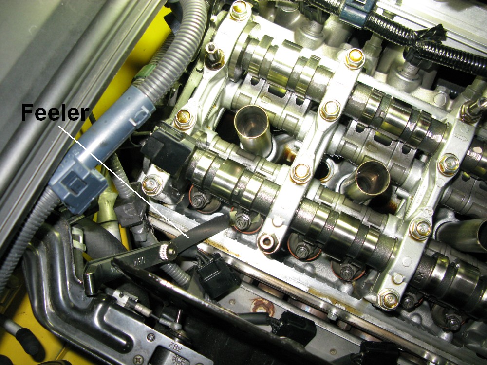
Cylinder # 1 Intake Valve Adjustment
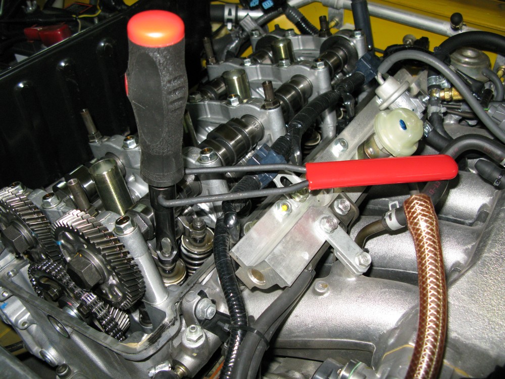
Note: The Valve to the Right is Also a # 1 Intake Valve
Adjusting the Valves
Each cylinder has 2 intake valves and 2 exhaust valves. The intake valves are on the intake manifold side and the exhaust valves are on the exhaust manifold side of the engine (no shit?).
Check the valve clearance with clean feeler gauges before loosening the adjuster lock nut. Many of the valves will be in spec and will not have to be adjusted.
Best engine performance will usually come with tighter valve clearance. A small gap allows the cam lobe to push the valve stem farther to open the valves more which allows better engine breathing. If you're tuning for top performance and don't mind checking the clearances more frequently you may want to set the low end of the adjustment range. If the clearance gets too tight the OBDII system may pop a check engine light. If it gets extremely tight the valves can actually begin riding the cam lobes full time or risk pushing the valve too deep into the cylinder head for a piston strike. Also with wear valves normally tighten up so I recommend shooting for the middle of the valve clearance adjustment range.
My feeler gauges came in .20 .25 and .30mm. On the intake valves we're looking for .21 - .25mm so I wanted to feel no drag on the .20mm feeler and a little drag on the .25mm feeler. I inserted both to check the intake valve clearances and those I adjusted I set the adjuster screw so I had just a little drag on the .25mm feeler, then inserted the .20mm and verified it slid in freely with no drag. You must make sure the feelers are flat in the gap--this is why you must have "pre-bent" feeler gauges. If you try to use straight blade feelers you will not be able to tell if the .20mm feeler slides freely--the bending feeler gauge will create some drag even when it shouldn't. Move the feeler gauges around and try to feel for the minimum drag that occurs when the feeler is level in the gap. Any twist of the feeler will generate more drag and make you think the gap is tighter than it really is.
If a valve needs to be adjusted leave the feeler gauge in place and put the adjustment tool (or 10mm box wrench) on the adjuster lock nut and turn it counterclockwise to loosen it. It will only need about 1/4 of a turn to allow adjustment. With the feeler gauge still in place turn the screwdriver part of the valve adjuster tool clockwise to shorten the gap and increase drag on the feeler gauge or turn it counterclockwise to increase the gap and decrease the drag on the feeler gauge. Normally a very small adjustment will be required--around 1/10th of a turn of the screwdriver so make small adjustments and check the feeler drag.
Comment from s2ki.com: if you aren't using the valve adjustment tool, and you felt like doing it the hard way, taking off the fuel injector harness all the way from the map sensor over through the fuel rail to the firewall REALLY helps get it out the way.
When you get the drag you want freeze the screwdriver, leave the feeler in place and tighten the lock nut to 14 lb-ft, then check the gap drag again to make sure it didn't change when you tightened the lock nut.
For the exhaust valves we're looking for .25 - .29mm so for my feeler gauges I want a very little drag on the .25mm feeler and the .30mm feeler should not even fit in the gap without considerable force.
When you've double checked the 4 gaps on cylinder #1 you can turn the crankshaft 180 degrees (cams turn 90 degrees) to set TDC for cylinder #3 (see below).
Setting TDC or Cylinders 3, 4 and 2
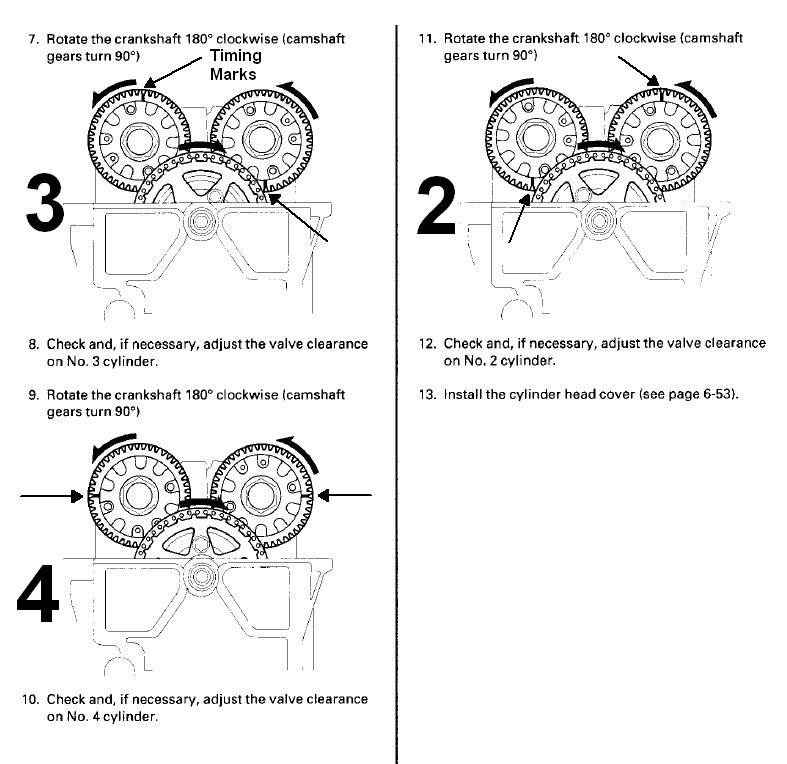
Note: Use the timing marks on the cam gears (highlighted with arrows above and black dots in the pics below) to accurately set TDC. For cylinder 3 set the exhaust gear mark to 12 o'clock (referenced to engine, not the car) and set the intake gear mark to 6 o'clock. Cylinder 4 is 9 and 3 o'clock. Cylinder 2 is 6 and 12 o'clock. Thanks go to Mac for the correction.
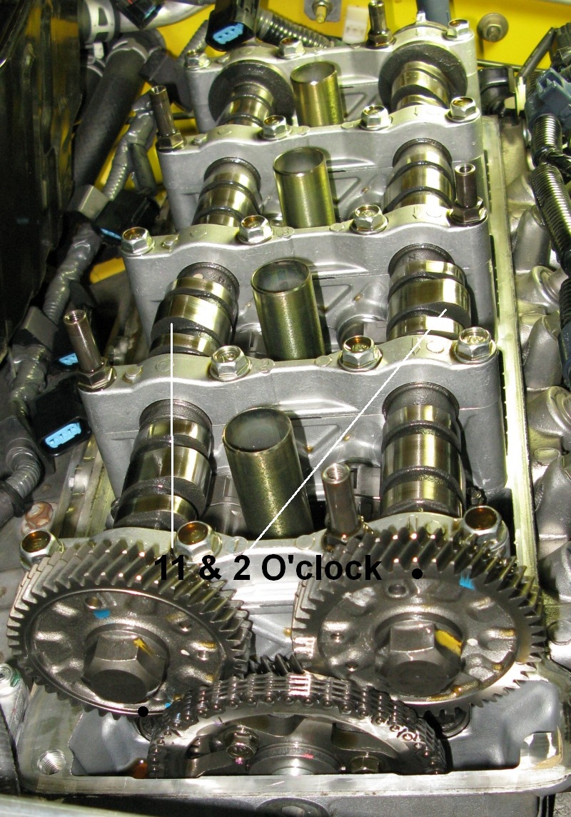
TDC Cylinder # 3
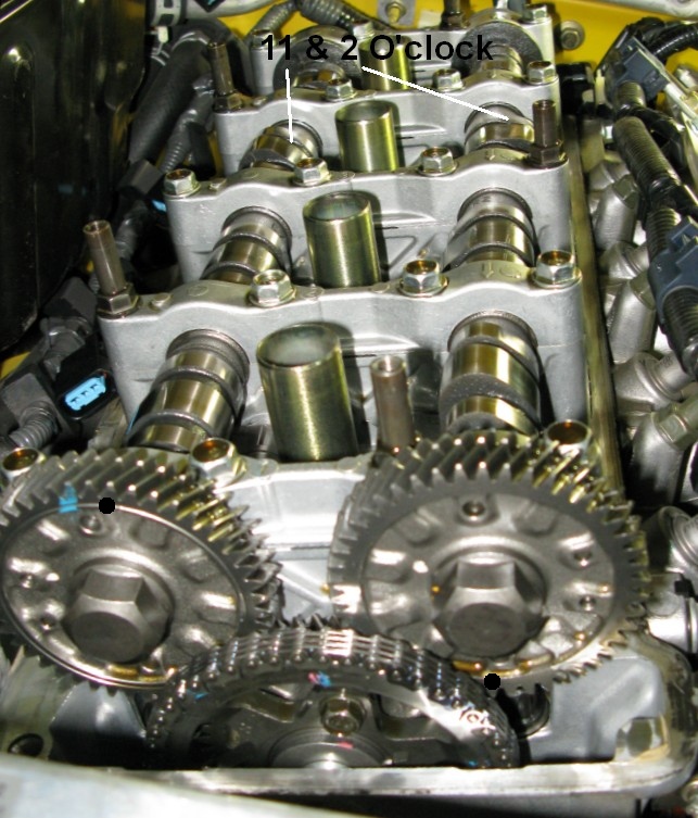
Note the black dots highlighting where the cam gear timing marks should be--12 and 6 o'clock.
Measure cylinder #3's four valve clearances and adjust as necessary. Its cam lobes will be at 11 and 2 o'clock.
TDC # 4
Adjusting Cylinder # 4 Exhaust Valves and Working Around the Heat Shield
Turn the crankshaft 180 degrees for cylinder #4's TDC.
Removing the battery heat shield will make it easier to adjust the exhaust valves but I didn't have any problem with leaving the heat shield in place. The heat shield's rearmost bolt is the tough one to access--it only needs to be loosened, not removed to free the shield. There is an opening at the back side of the shield. You can work through that from the top and steady the wrench that way while turning it from above to loosen it or it is a straight shot to reach it from below the car.
TDC # 2
Repeat for cylinder #2.
When you finish you should consider going back and checking cylinder #1 because you'll gain enough experience feeling the gap drag that you may be able to do a better job at judging the valve gap on the cylinder you started with.
When complete remove the wrench and socket from the crankshaft.
Cylinder Head Cover Installation
Install the spark plugs and torque to 18 lb-ft. Do this now to keep things from falling into the spark plug holes.
Warning from NGK: For spark plugs with special metal plating do not use anti-seize on initial Installation. All NGK Spark Plugs are manufactured with a special trivalent Zinc-chromate shell plating that is designed to prevent both corrosion and seizure to the cylinder head; Thus eliminating the need for any thread compounds or lubricants.
Clean the top of the spark plug tubes, the mating surfaces of the cylinder head and head cover and around the 5 head cover bolts.
If you are replacing the cylinder head cover gasket it's a good idea to wipe it down with a little motor oil before pushing it into place. Oiling new spark plug hole rubber seals is a good idea too--it will help ease the fitment of the head cover and prevent damage to the seals.
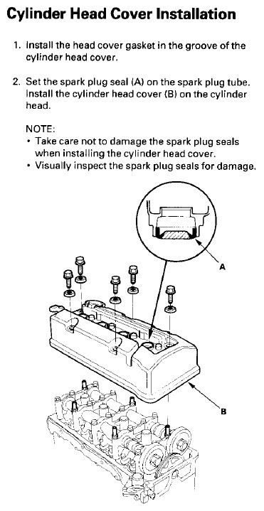
The Shop Manual page above seems to imply you put the spark plug hole seals down over the spark plug tubes, but the picture shows them installed in the cylinder head cover first. I replaced a couple of my spark plug hole seals. I used a large screwdriver to pry them out of the head cover then wiped some motor oil on the new seals and pressed them into the head cover by hand. I had to use a rubber mallet on one to get it to fully seat. I then installed the head cover and made sure the spark plug tubes slid into the rubber seals' holes--be careful not to damage them when putting the head cover in place.
Push the thick electrical cable down and back out of the way with one hand and put the cylinder head cover into place with the other.
Gently wiggle the head cover down into place, watch the spark plug rubber seals when doing this.
Closely inspect the spark plug holes and seals once the head cover is sitting flush with the cylinder head.
Gently move the coil harness back into place.
Look around the edge of the head cover to make sure all wires and tubes are clear of the head cover.
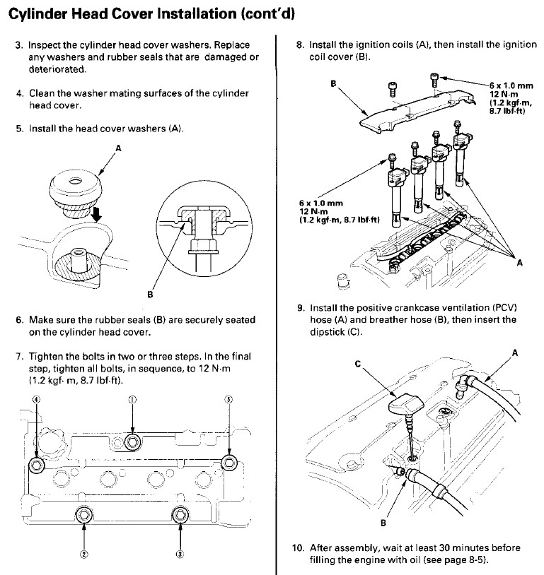
Wiggle the cylinder cover bolt rubber seals into place to make sure they have slid down into the head cover and are fully seated. Tighten them all finger tight. Bolt them down in three rounds (a little each time) following the star pattern shown above in Step 7 to 8.7 lb-ft.
Reinstall TDC1 sensor, torque both TDC sensors' 10mm bolts to 8.7 lb-ft and plug in the electrical connectors to TDC1 and TDC2 sensors.
Clip the thick electrical cable back to the firewall.
Insert the coil packs and clip on their electrical connectors--make sure you hear a solid click for each one. Install the 4 coil pack 10mm bolts and torque to 8.7 lb-ft.
Reinstall the ignition coil cover and secure it with 4 small hex bolts.
If you removed it, reinstall the battery heat shield and torque the bolts to 7.2 lb-ft.
Reinstall the PCV valve, breather hose, and oil dip stick.
Double check all the electrical connectors around the cylinder head cover. Many have left a TDC sensor, VTEC solenoid or other electrical connectors off.
Verify you removed the wrench and socket from the crankshaft! WARNING - Do this twice to be sure it is off!
Closely inspect the engine compartment for tools and spare parts.
Wait at least 30 minutes after bolting the cylinder head cover down before starting the engine to give the rubber seals time to seat and seal.
Fire up the engine and enjoy the sweet harmony of the freshly tuned S2000 engine.
Once it's running take a good look at the engine compartment and look for any leaks/problems.
If the engine doesn't sound right or won't start verify all the electrical connectors are secure and double check both the TDC sensors on the head cover.
Rob Robinette